Page incomplete (requires further review)
¶ Introduction
¶ What is Therion?
Therion represents a 3d-printing augmentation project that aims for achieving thin-film deposition capabilities on a Voron Trident printer, enabling at-home prototyping and quality control of complex custom-3D-printed multilayer PCBs, printed plastic pieces with inner metal traces, shielding for reliable electric work (improving cable-management drastically) or emf shielding.
A theoretical research of a new technique of additively depositing conductive traces on 3D-printed substrates using plasma ion bombardment.
This project also aims for combining metal plating capabilities with the improved print quality and capability by tapping into the tremendous potential offered by vacuum printing.
films could be virtually made of almost any metal or ceramic compound, using a modified plasma gun toolhead for depositing films. A toolchanging system will be implemented, rapidly switching between traditional printing and thin-film deposition.
Therion implements a modified physical vapor deposition (PVD) technique, which we have branded: plasma-enhanced inductive physical vapor deposition (a similar version of which already exists in industry). It uses induction heating for efficient sublimation of surface atoms and ECR microwave ionization with gas precursor plasma for high deposition rate of dense, quality thin film.
¶ Problems Therion solves
- Quality desktop multilayer PCB manufacturing and prototyping for small and big projects
- Printed traces inside the plastic parts drastically improves cable management
- Metal plating allows for shielding plastic pieces against EMF radiation.
- Decorative metal plating
- Possible minor optic modification of lenses using partial-mirror plastic lenses (tinted glass).
- Easier prototyping, eliminating 3rd party PCB manufacturing altogether
- Future improvements can allow for high-end aerospace grade filament printing (such as PEEK or PEI ), making use of the advantages offered by vacuum additive manufacturing
- Minor surface modification/cleaning of the print bed or other parts using plasma cleaning/etching
- Modification of the plasma barrel toolhead can permit precise plasma cutting and 3 axis CNC-machining of flat aluminum and steel panels
¶ Brief introduction in plasma physics
This section is meant to be seen as an introduction in plasma physics for anyone not familiar with the subject. This section can be skipped if already aquainted with the subject, as it's not vital for project understanding.
The last couple decades have seen a dramatic increase in plasma related research. Currently, it's one of the most studied, if not the most studied field in physics and manufacturing engineering. With extensive academic research carried over the last years and wildly available study materials on the subject, there are a couple reasons why plasma has peaked in interest.
- first, most manufacturing processes carried today in the PCB industry are plasma based, with total market price of about 70-73 billion USD in 2024, projected to reach 100 billion by 2032.
- second, fusion related research has peaked in the last couple decades, requiring extensive plasma research and innovation for further design improvement. It is projected that once fusion reactors are developed and enter the market, they will dominate any other alternative energy reactors. Plasma will also become a critical component of future space exploration projects, our civilization needing plasma research to grow and evolve
- third, and most important, it's estimated that more than 99% of matter in our universe is made out of plasma, our planet being one of the few places where plasma doesn't occur naturally.
¶ What is plasma?
Elements have a default neutral state, otherwise searching for ways to equalize their number of electrons and protons. By using high energy methods, it is possible to strip electrons form atom electron clouds, obtaining a ion, a positively charged particle, a chemically and physically unstable species which is highly reactive, having the ability to strip electrons from other nearby neutral particles in order to achieve neutrality. Having a high percentage of ions in a gas cloud can eventually bring about the creation of a plasma.
Generally, when a high energy electron hits a molecule's electron cloud, kinetic energy is transferred, potentially exciting one or more electrons to a higher energy level. This higher energy state lasts briefly, electrons typically losing energy via electromagnetic radiation (photons which create the plasma "glow") or sometimes through processes of dissociation, excitation or dissociative ionization, producing a positive ion x+ - the molecule's electron will continue to migrate away from the nucleus, causing dissociation and, eventually, dissociative ionization (figure 1).
| Figure 1: diagram showing the steps in the ionization of an argon atom. From left to right: The last step from the bottom right corner shows the case in which a plasma ion recombines with a free electron, achieving yet again neutrality. |
|---|
Electric arc discharge as well as microwave ECR excitation represent some of the high energy methods used for creating plasma. Both methods use the transfer of kinetic energy from "hot" electrons (energetic electrons) to the gas atoms in order to excite them, a fraction of them reaching plasma state. These two methods use different energy transfer techniques, such as ohmic heating, ECR ionization etc.
Plasma industrial processes, especially plasma deposition processes are non-equilibrium thermodynamic processes (the system is inconsistent in time, experiencing various forms of matter and energy exchange processes between many other sub-systems) which exploit the instability of plasma ions for various applications.
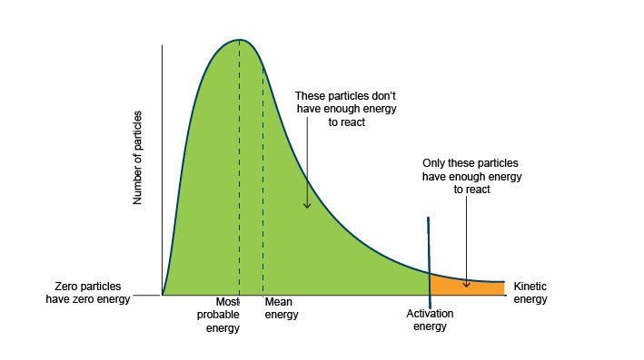
It is important to mention that particle energies inside a plasma follow a normal distribution (a kind of a gaussian distribution), called a maxwellian distribution. The distribution curve as well as average particle temperature (energy) depends on power input, gas species as well as working pressure etc., moving either to the right or left, depending on these criterions.
 |
|---|
| Figure 2: maxwellian distribution (following a “normal distribution” of electron thermal energies) |
The ionization process formula for one Argon atom can be written as:
Ar(g) + e- → Ar+(g) + 2e-
or, if the electron is energetic enough, it can remove more electrons
Ar(g) + e- → Ar2+(g) + 3e-
Not every ionic gas or fluid is considered a plasma. There are a few criterions that need to be fulfilled in order for a gas to be considered a plasma. These criterions are:
- “A plasma is a quasineutral gas of charged and neutral particles which exhibits collective behavior”, a short explanation taken from “Introduction To Plasma Physics”, by F. Chen, reveals that
Consider the forces acting on a molecule of Nitrogen. Since the molecule is neutral, there is no net electromagnetic force acting on it, and the force of gravity is negligible. The molecule moves undisturbed until it makes a collision with another molecule, and these collisions control the particle’s motion. A force applied to a neutral gas, such ass from a loudspeaker generating sound waves, is transmitted to the individual atoms by collisions. The situation is totally different in a plasma, which has charged particles. As these charges move around, they can generate local concentrations of positive or negative charge, which give rise to electric fields. Motion of charges also generates currents, and hence magnetic fields. These fields affect the motion of other charged particles far away.
It is exactly these electrostatic forces created by electric potential differences between local ion and electron concentrations that cause consistent uniform motion between ion and electron species. These particles exert forces of attraction on eachother, giving them the ability to shield potential changes or local concentrations of charges because of these very movements and forces. Therefore, equal electron and ion population densities are necessary to maintain quasi neutrality, thus ni = ne = n (where n stands for ni-ion density ne-electron density and n is the number representing these densities.
- Another criterion is that the total number of collisions between plasma particles is low enough so that the recombination rate of ions and electrons stays low. If electrons knock with positive ions, the electron will get absorbed by the ion, becoming a neutral particle once again. This is not a wanted effect, as the energy required to maintain a plasma increases exponentially with pressure. Also, plasma motion should be mostly dominated by electrostatic forces, not usual hydrodynamic mechanics, given the high collision rate of high pressure systems.
Plasma electrons and ions generally have very high thermal energies, in the tens of thousands of K. For this reason, plasma particles generally have low mass but high energy density, meaning that they can easily excite and vaporize surface atoms.
¶ The main manufacturing process implemented by Therion
“The formation of a condensible vapor by physical mechanisms and subsequent deposition of this material onto a substrate as a thin film or coating is referred to as physical vapor deposition (PVD) (Mahan 2000, Rossnagel 2003, Thornton 1988). The formation of a vapor refers to a phase transition of the filmforming material from a solid or liquid phase into a gaseous or plasma phase. PVD is a broad field and various processes are applied to create film-forming material and to achieve thin film deposition.” (Foundations of physical vapor deposition with plasma assistance). As it's frequently mentioned, the term vapor used here is sort of a misnomer, in comparison to vapor-gaseous state released through thermal excitation, the term refers to any gas-like plume of particles that is obtained through electric-plasma/thermal excitation phenomena.
The main processes are plasma ion sputtering (vacuum) and plasma jet evaporation (for atmospheric plasmas):
-
Plasma sputtering - used widely in lens production and metal film deposition, it is used for quality film production and can be scaled down to accommodate a printer. The concept it's quite simple: a magnetron accelerates electrons, producing plasma ions inside a vacuum sealed chamber. The plasma gas is usually argon. A strong permanent magnet positioned on top of the magnetron has the purpose of confining both electrons and ions within a small volume close to the target (target-usually made out of metal, represents either a wire filament or a wafer which will coat the substrate underneath), increasing their confinement time (the average time taken by one electron to escape the magnetic confinement area). The ions, being magnetically accelerated close to the target knock metal atoms from the crystal lattice of the target. These atoms are hence ballistically launched radially in all directions, coating the substrate. The deposited film is a dense, quality film given that coating is done at atom level.
-
Thermal evaporation - used in vacuum, due to higher efficiency and lower corresponding melting temperature of the target, achieving surface sublimation. This design typically incorporates metal filaments, warmed up beyond their melting temperature, creating a vapor cloud that deposits on the opposing substrate. This process is typically line-of-sight, unless there's additional augmentation given by vapor cloud ionization techniques.
The main difference between these methods is the degree of atomization of the vapor plume, energetic processes (such as plasma sputtering in vacuum) yielding high energy levels of ion species, which creates better coatings. films are effectively built atom-by-atom, causing high, consistent film density. The overall atomic structure of the bulk target is reproduced in high enthalpy plating methods (high-energy) on the substrate, while lower enthalpy processes cause higher oxidation (open atmosphere process), porosity and less atomic reproduction of the bulk.
¶ Therion-concept
Therion will incorporate a combination of the methods presented above, depending on the working pressure and power feed. We will now explore each concept and how they would affect the design.
¶ design concept
First, we need to establish in what way the project design differs based on the concept we'll incorporate henceforth. The main difference arising in project design would consist out of respective power feed used for brute ionization against working chamber pressure - in sputtering processeses, increasing power feed increases plasma density, which can overcome higher working pressure limitations, but decreases overall efficiency, while thermal evaporation works at higher working pressures with the same power feed, but at lower film quality.
An important caveat of sputter chamber design is the need of lab grade vacuum pump equipment, compulsory at pressures lower than about 0.3Pa, otherwise deposition will yield lower quality film coating as well as lower deposition rate.
¶ Plasma sputtering
If plasma sputtering is to be used, the pressure inside needs to stay low, about under 0.1Pa. At high vacuum pressures, equipment gets expensive fast, much slower, outgassing starts to matter a lot more and not price optimal, overall resulting in a small increase in quality, not worth the purpose of this project.
The ionization energy - the minimum energy required to remove the most loosely bound electron from an isolated, gaseous atom or ion - also differs with each gas precursor. This energy is inversely proportional (in noble gases) to the atomic number, Z.
Most common sputtering gases are noble gases, thanks to their inertness and availability, Argon being widely used in aluminum welding (TIG welding). Other noble gases are either expensive or have a ionization energy set too high for the scope of our project, Argon being the most suitable gas for our apparatus. Other noble, as well as non-noble gases will be made use of in the future, giving rise to more manufacturing posibilities.
| Noble gas | atomic number(Z) | ionization energy(eV) |
| Helium(He) | 2 | 24.6 |
| Neon(Ne) | 10 | 21.6 |
| Argon(Ar) | 18 | 15.8 |
| Kripton(Kr) | 36 | 14.0 |
| Xenon(Xe) | 54 | 12.1 |
| Radon(Rn) | 86 | 10.7 |
Other non-noble gases can also be used for plasma etching, an industrial application in which material is removed from a substrate using specific chemical reactions between plasma and the substrate, making use of the plasma's instability to kick-start aggressive surface chemical interactions, creating volatile compounds which then evaporate at room temperature.
The deposition rate is fairly slow, ranging from 0.1 nm/min up to several hundred nm/min, but the energy of each sputtered metal ion is really high, several eV, increasing surface adatom mobility (the ability of atoms to migrate and fill gaps and inconsistencies once absorbed on the substrate surface) and thus, surface film quality.
¶ Evaporation
For thermal evaporation deposition, pressure has to be kept in the transitional molecular flow (molecular flow - at lower pressure under about 0.5-1Pa wall collisions start to dominate, inter-molecular collisions being significantly lower which virtually excludes viscous flow) 0.1-1Pa range, reaching a maximum of 2Pa in some setups. The process is line-of-sight, yielding lower adatom mobility (surface migration of atoms) and thus, lower film density.
| |
|
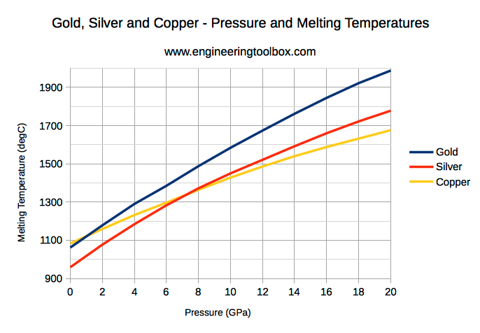
| Figure 3: pressure vs melting temperature graph; the melting temperature drastically increases with higher temperature |
|---|
Deposition is much faster than it is in sputtering systems, implementing surface heating close to the target's melting point, which causes surface sublimation and vapor formation which will then coat the substrate (at lower energy compared to sputtering).
The melting temperature of most metals is proportional to the the pressure inside the chamber, decreasing by couple hundred degrees with higher vacuum. Hence, lower working pressure enables more efficient heating of the target, as well as longer mean free path, in turn increasing quality.
Moreover, a large range of deposition speeds can be achieved and controlled, requiring careful surface temperature monitoring.
Exposed structural parts inside the toolhead would have to be covered with a protection film so that deposits don't form on the surface, possibly corrosion structural elements.
This process is line-of-sight only if the chamber allows for collisionless deposition, otherwise overall atom vapor movement would be governed by viscous flow, producing chaotic atom travel paths, decreasing film quality and deposition speed. If the vapor is ionised (by say, an ECR unit-a microwave magnetron), then the thermal energy of the vapor atoms drastically increases, reaching high ionization density at efficient power consumption, especially in high-vacuum setups.
Vapor pressure exhibits an exponential dependance with temperature, being approximately
pv ∝ exp(−ΔHv/RT)
---where Hv is the heat of evaporation and R the universal gas constant
Exponential dependence points to an important caveat in evaporation systems design - a slight variation in target temperature leads to a greater increase or decrease in vapor pressure, and thus trace thickness.
For a given temperature, the sublimation
rate increases rapidly as the operating pressure is reduced from
atmospheric pressure [gudmensson].
¶ Concepts integrated in our design
Plasma-enhanced thermal evaporation deposition processes have been used in industry, implementing both evaporation and plasma to augment the system - often yielding high deposition rates similar to evaporation processes and high vapor energy, comparable to spputering.
at pressures under about 0.5Pa, sputtering and sublimation both start to coexist inside the chamber. Using the right base target surface temperature ensures controlled, conistent sublimation, plasma aiding with additional energy needed to launch atoms onto the substrate. For our project, both sputtering and thermal evaporation will be implemented, suiting more target types and compositions, allowing for sputtering of ceramic coatings and evaporation of metal films.
¶ Plasma barrel design schematic
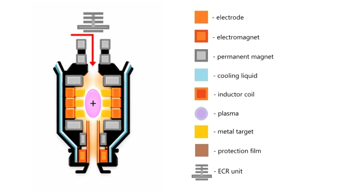
The design incorporates a barrel-like appearance similar to that used in atmospheric plasma jet guns. Argon or other process gases are injected through an inlet (a) into the process chamber (b) where ionization happens and plasma is concentrated via a set of magnetic mirrors formed by the magnets coaxially attached to the barrel. an ECR unit (a microwave amplifier PCB or a magnetron with near ECR characteristic frequency) of high power is placed on top of the assembly, allowing for line-of-sight operation of the magnetron antenna (microwaves are coaxially directed through the barrel tube).
 |
|---|
| Figure 4: Design schematic and legend |
Zone (b) is where thermal evaporation takes place. The metal-to-be deposited is placed as a ring (disk or toroid) inside a ceramic hearth between two in phase inductors placed face-to-face. The metal is heated through induction heating near its melting point, and given that in HV the boiling point is close to the melting point temperature, sublimation of surface metal atoms starts to produce. Thus, a metal atom cloud forms, which is ionised and atomized by the microwaves coming in from the ECR unit. atoms gain high temperature and kinetic energy which helps enhance the deposition process. high plasma densities can be achieved through careful design and choice of high power ECR unit. Often ionization percentages ranging between 80-90% can be achieved, drastically
 |
|---|
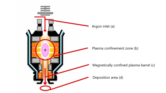
| Figure 5: Process path of plasma through the apparatus. Main areas: (a)->(b)->(c)->(d). Gas enters in the assembly through area (a), ionizes the metal vapor plum in (b), gets focused in (c) and exists through (d), coating the substrate |
increasing the quality of the deposited film. The in phase inductors act as one single strong inductor, interfering constructively right in the middle, where the metal disk is found. Thus, efficiency is increased and heating of the metal is achieved more effectively. The most important advantage of using two paired inductors is the ability to slide and switch the metal disk right through the “sleeve” created by the gap between the two inductors. This way, more than one metal can be plated. Stacking more pairs of inductors allows for alloy plating (the temperature within each disk being closely monitored and controlled) and lots of other applications. The metal disks will be placed on a ceramic disk hearth which will be actuated via a stepper motor, allowing for easy and precise switching between the disks.
The metal ions are then magnetically confined on one central axis ( c), forming a plasma beam which is shot through the barrel outlet (d). microwave electrons launching from the ECR antenna are also confined on one axis by the magnets found in area (a). A combination of electromagnets and permanent magnets will be used, making use of efficient power usage and simple calibration of magnetic force lines and ion trajectory. The total magnet contingent will form one continuous magnetic mirror which will trap electrons and ions inside area (b), increasing transit time and forcing ions back, thus increasing energy efficiency and plasma density.
The barrel will most likely be built out of some sort of ceramic (alumina or other material), given its high compressive strength, low mass, high melting point, chemical stability, dielectric properties (electric insulation) and low vapor pressure (very important in high-vacuum systems and UHV making use of thermal and chemical vapor deposition). the ceramic barrel will likely cover areas (a), (b) and ( c). Area (b) will most certainly be made out of some sort of ceramic tubing hearth, given that many ceramic hearths are used in thermal evaporation deposition systems (typically zirconia, alumina and sometimes refractory metals [gudmundson]).
¶ Industrial design
Similiar design principles have previously been implemented in industry, making for high plasma density at relatively medium pressure levels.
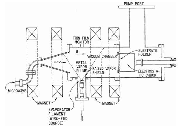 |
|---|
| Figure 6: Plasma enhanced thermal deposition apparatus |
The metal target is brought close to its melting temperature, producing a metal vapor plume. The ECR unit ionizes the plume, achieving high ionization percentages (close to 100%), achiving high quality film. Magnetic confimenet makes sure both the microwaves and the ions move parallel to the field lines, bombarding the substrate with metal ions. Increasing the ECR power feed also increases the plasma density of the plume, increasing quality and efficiency. a quartz crystal film monitor keeps track of film thickness by measuring the change of the resonating frequency of the crystal. This deposition technique has proven to be very efficient, yielding high film quality as well as high depotion rates (when compared to sputtering). Moreover, this technique has proven to be compatible with higher process pressures, ranging from 10-2 to 5*10-1 Pa.
Therion's design implements similar principles, using induction heating to supply the necessary thermal energy to create the metal plume which starts the deposition process. The magnetron (ECR unit) supplies the microwaves which then transfer their kinetic energy to the vapor atoms in order to ionize them. An assembly of magnetic mirrors is implemented in both designs, concentrating plasma near the plume. In industrial thermal evaporation deposition processes, it has been proven challenging to deposit alloys, requiring the use of multiple targets which have to be heated to different temperatures in order to closely control the vapor production rate of each target, and thus control the composition of the deposited alloy.
In our design, coaxial inductor pairs can be implemented on the same ceramic heath, maintaing precise temperature contro of each of their individual targets.
In plasma enhanced thermal evaporation deposition systems, using a process gas like Argon is not compulsory. In our design, Argon will be used to:
- keep the system clean by purging metal residue off the barrel walls post-deposition.
- aid the deposition process by bombarding the metal surface and sputtering atoms
- gas shielding from oxidation and impurities (hydrocarbon molecules) by flooding the space nearby with Argon (inert gas)
- surface cleaning of the substrate before plating
- Adding reactive gas (like Nitrogen) which creates complex film species (nitrates, oxides etc.)
Also, even though industrial settings are able to achieve high ionization, close to 100%, in order to achieve this, careful industrial design and laboratory grade equipment is required (true ECR units, not imprecise magnetrons). Therion will likely achieve ionization percentages in the 50% range, depending on geometry and magnetron power feed. Even so, 50% is still highly workable, enabling dense, quality film formation (electronics grade), leaving a lot of room for future improvements on the figure.
¶ (A) - Argon inlet
The argon inlet is placed as a cap on the top of the barrel, containing mainly a throttle valve tied to a tube through which gas is let into from an outside source. The throttle valve will likely be placed on the atmospheric side, in combination with a basic vacuum gate valve which will restrict any unwanted parasitic gas flow outside of normal operation, which can happen in some lower quality throttle valves not meant for flow restriction. Pressure through the tube will be measured, and based on the total conductance of the supply tubing and system, the flow through the tube will be calculated. Reactive gases that can be used range from Argon to Helium and nitrogen. Nitrogen can be used to create nitrates. Oxygen may also be used to create oxide films, but given the high flammability of oxygen it would be recommended to use oxide base targets instead.
some aluminum or ceramic tubing on the top cap of the barrel, together with a pair of permanent magnets will make use of directed confinement to keep gas ions and microwaves on one trajectory, without leaking microwaves through the walls. The ECR unit (likely magnetron) will be placed on top of the cap with the purpose of supplying the required microwaves.
¶ (B) - Plasma confinement zone
A strong pair of neodymium magnets placed on the top and bottom end of the confinement zone will increase electron and ion dwell times, achieving more efficient microwave absorption of metal vapor atoms. The ions and electrons will complete cyclotron orbits along the field lines, losing momentum near the magnets where the intensity of the field increases, thus forming a magnetic mirror in combination with the other permanent and electromagnets placed coaxially along the barrel tube. The intensity of the magnetic field passing through the electromagnets is increased, allowing for manipulation of the magnetic mirror intensity and of the loss cone.
Only energetic ions will be able to escape through the loss cone into zone (c ) (and then in zone (d) and onto the substrate), thus allowing for high adatom mobility of deposited surface atoms, filling gaps within the film and reducing porosity (therefore increasing quality).
The inductor coil is made out of hollow copper wire allowing for water to run through and cool down the inductor. High power induction heating applications create a lot of residual heat within the inductor wire which can potentially melt the wire and create hot spots because of the skin effect (explained bellow). As mentioned above, a pair of two inductors placed face-to-face will act as one inductor heating the metal target disk, the intensity of the field peaking halfway between the two inductors, where the target is places. Therefore, the metal disk can be off-centered from the center of an inductor without causing losses and heating inefficiencies of the metal.
The geometry of area (b) will be similar to a cross, plasma extending and covering the zone where the target is placed so that a bigger plasma cloud can form, covering more of the target's surface.
It is important to mention that there will be up to three individual ceramic heath branches (a branch represents one ceramic heath on which targets have been placed) between which the user can choose and switch, via the stepper motor placed on the back of the barrel.
¶ Inductor coil
The inductor coil is used in this design for precise surface heating of the metal target used. Thanks to the skin effect, most of the current induced inside the target is focused in a narrow volume, close to the surface of the conductor.
| |
|
| Figure 7: diagram showing the fields induced inside a metal conductor through which AC current is circulating (image from Skin effect - Wikipedia) |
|---|
This effect is caused by the inability of currents and magnetic fields close to the outside of the metal to shield it from the induced current.
In the center, where the opposing fields are strongest, the current reduces close to zero. Therefore, it is easy to precisely control the degree of heating and evaporation of the outside metal layer, given that the skin depth is proportional to frequency-higher frequency creates shallower skin depths, raising the resistance of the skin layer which in turn raises the temperature(this effect is AC specific). Bringing the surface metal atoms close to melting temperature also increases the mobility of these atoms, freeing themselves from the crystalline lattice they occupy and allowing for easier vapor formation (either by plasma or by sputtering).
In this specific design, induction heating could also enable easier alloying of metals by precisely controlling the vapor formation and pressure of the metals being used. It could also allow for individual deposition of the metal targets. Once surface atoms reach about 90% of melting temperature, energetic plasma ions will further transfer their high kinetic energy to these atoms, vaporizing or sputtering them-depending on the pressure used inside the chamber.
Given the high energy density of plasma, but low mass, only surface level heating is achieved, further managing deposition rates.
| |
|
| Figure 8: thermal energy transition in AC coupled metal showing the effect of the skin effect in induction heating. 20kHz vs 81KHz (image from) |
|---|
For efficient heating of the metal element, the distance between the target and the inductor would have to be fairly small, around couple mm. Thermal dilatation would also have to be considered. Moreover, the shape of the target would best allow field lines to sit perpendicular to the surface of the metal, for high efficiency.
Hollow, water cooled inductors would be best, minimizing coil overheating, but other conductive cooling methods that don't require hollow conductors can be implemented. Efficiency would also depend on the electric resistance of the target, Higher resistance yielding better results. It's essential that the temperature of the bulk metal doesn't reach melting point, preventing structural deformation.
Also, induction heating would only work for metal targets, ceramics or polymers would have to be exclusively sputtered on the substrate surface.
A strong permanent magnet placed under the target and the inductor will purposely concentrate and confine plasma near the target, enabling fast removal of surface atoms from the crystal lattice.
The surface heating resulted from the skin effect combined with hot electrons and ions colliding with the metal evaporates and sputters metal atoms towards area ( c), onto the substrate. Thus, deposition is achieved through mainly evaporation deposition, but also sputtering.
As mentioned above, future barrels can implement one of two designs - 1. one pair of inductors for depositing metal individually (pros: simple, clean deposition of metal; cons: no alloy deposition) or 2. multi-pair inductor branches which can switch between branches containing up to three individual metal targets which can be closely temperature controlled to achieve precise alloy deposition (pairs such as copper, iron and nickel).
¶ Managing deposition rates and target temperature
For the purpose of the project, it is vital for the deposition rate of metal to be controlled and managed. Evaporation rate of metal surface atoms is largely exponentially dependent on surface temperature, staying close to 0 at temperatures bellow the boiling point and drastically increasing at temperatures near or over this threshold. Careful, controlled deposition allows for the design of intricate PCBs, either HF, RF or power circuits. In order to achieve this, the width and thickness of the deposited film has to be controlled. The use of empiric methods, mathematical models as well as precise measurement instruments can all help achieve this.
For temperature measurement, an industrial IR precision sensor, with a maximum range between 1000-1500 degrees Celsius would be optimal. Close, indirect measurement can thus be achieved without the risk of damaging the sensor, which will likely be placed on the outer shell of the barrel, where the metal target lays uncovered inside the ceramic heath. The instrument will be mounted on an aluminum frame surrounding the barrel, which helps both structural integrity, as well as for sensor mounting.
Given that convection is limited in vacuum, cooling of the target would be achieved mainly through the ceramic heath, which (if made out of thermally conductive ceramic) can be water cooled to keep the temperature in check, or to change the evaporation rate of the target.
A PID algorithm modified for vacuum conditions will likely be used for controlling the power feed to the inductor, making sure the temperature of the metal doesn't raise drastically over the target temperature. Careful temperature control has to be implemented in order to keep trace quality in check - uneven metal distribution over the length of the trace can lead to hot spots during use which can damage the PCB and increase electrical resistance (lower trace quality) or it can lead to problematic signal reflections in RF circuits (unmatched impedance).
¶ (C) - Magnetically confined plasma barrel
The barrel is where freshly ionized metal ions escape to, being magnetically directed through the length of the barrel to the substarte. A set of permanent magnets and electromagnets complete the magnetic mirror, the electromagnet aiding in the constant adjustement and proper functioning of the magnetic field lines so that plating and confinement can be done efficiently.
The barrel tube will likely be made out of some kind of ceramic, probably alumina given its high compressive and thermal strength, durability, lightness and insulation properties, having no role in influencing the magnetic field lines.
aluminum shielding cylinder sheets will likely be clamped wound the tube, in between the magnets to aid in microwave shielding, against the ECR unit.
a metallic zero aperture iris diaghragm placed on the bottom end of the tube will adjust the width of the deposited trace, achieving widths as low as 0.1mm or lower (suitable for signal trace applications as well as power circuit applications).
¶ (D) - Deposition area
As it has already been mentioned above, film qualilty and overall microstructure depends heavily on subtrate temperature, film thickness (deposition rate), and most importantly particle potential energy (or deposition energy for short). Increased substrate temperature improves atom absorption, enabling deposited atoms to fill voids withing the film microstructure. High subtrate temperatures can cause more harm than good, increasing atom diffusivity within the film, creating large recrystallized (aided by low deposition energy) grain structures which make for worse film quality, often resulting in a rough finish. All substrate types start degrading and deforming mechanically after a certain temperature threshold (typically after reaching the glass transition phase), some faster than others, reducing the substrate temperature range that can be used in design.
Film thickness is directly correlated to vapor energy, thick coatings and high deposition rates often indicating low atom temperature, only a few eV or lower than one eV. Evaporation is considered a high deposition rate process, given its typical low deposition energy, often below one eV, in contrast to spputering which often has a hundredfold or higher increase of that figure. Lower deposition rates allow for higher energy distribution within the vapour plume, also making for lower energy consumption and higher quality. Plasma enhanced evaporation sits anywhere in between, depending on the nature and energy of the plasma source.
A generalized temperature figure is used, linking melting temperature, substrate temperature, ion current density as well as the potential energy of the deposited particles
Deposition energy is much more energy is much more relevant, film growth depending directly on it, which allows for direct separation between microstructure types solely on it [goudsson]-low substrate temperature and deposition energy results in fragile, porous, columnar growth, typical of low energy deposition applications. Higher energy flux (E) results in a much more dense, quality thin film common in spputering. Higher substrate temperature only makes things worse from here on, deteriorating quality.
Considering all of the above and implementing design concepts inside our own project, it is important to keep printed pieces' temperature as high as possible (a couple degrees lower than the glass transition temperature, which sits just around the right temperature in ABS, improving film microstructure) via heat transfer aided by the printer bed. Also, distance between the target and the substrate has to be kept as low as possible, improving quality, efficiency (less particle collisions results in lower energy loss) and higher deposition rates.
Also, a more powerful magnetron improves energy flux, which leads to denser films and thicker coatings. Also, vapor partial pressure has to be kept low enough inside the barrel (including Argon flux) so that collisions don't dominate inside.
¶ Close-Space Sublimation of Single-Crystal Metal Films
CSS (Close-Space Sublimation) principles and design could be implemented in Therion, using epitaxial film growth for higher deposition rates and better quality.
important tradeoffs are the need for milimeter (a maximum of about 30mm) spacing between substrate and target source, which allows for much higher quality film growth at working pressures up to about 10Pa. Plasma confinement would be a bit more challenging in these conditions, but not impossible. Another important tradeoff is the need for high substrate temperature, enabling high adatom mobility which promotes epitaxial growth. Trace thickness sits at around a couple um, which coincides with the ECR's unit microwave skin depth penetration within a metal, which is also about 1.2um.
A base metal layer coating could provide the necessary foundation for inductive coupling of the microwaves provided by the magnetron, and the deposited trace. Thus, induction heating of the trace skin layer can bring about substrate temperatures in the 400-600C range, sufficient for CSS deposition and crystal "seed" growth (a base seed metal crystal which promotes growth in the same crystal orientation). Thus, precise localized microwave surface heating could be enough to provide the necessary substrate temperature, without needing ABS to be heated up beyond its melting temperature-even though interface temperature between ABS and coating could sit at around 250C, despite low polymer conductivity, degrading the substrate. Thus, either a more resistant thermoplastic filament has to be used, or pulsed microwave operation needs to be implemented.
Thus, ECR and CSS techniques can both be used to aid one another, in a potential design.
¶ Plastic substrate exposure to plasma
Many polymers used in 3D printing (including ABS) suffer from surface degradation following either prolonged UV exposure (yellowing and embrittlement) or plasma ion degradation.
Energetic species (such as plasma) break the bonds between molecules, creating polar compounds which promote adhesion and surface degassing. Thus, plasma surface activation and etching create a rougher surface, free of contaminants which helps with adhesion and deposition. Substrate temperature has to be kept moderate, keeping mechanical degradation and embrittlement at a minimum.
¶ Electric feedthroughs
Ideally, electric feedthroughs should be leak-free, with no micro-leaks created where the copper pins have been pressed into the ceramic/plastic isolation. FR4 circuit boards have high outgassing rates because of the binding resin that they're made of, so they cannot be used as a medium between vacuum and atmosphere. microscopic leaks can be managed and outpowered by the pump, provided the leaks are small and long enough to reduce conductivity and resist the pressure difference. A thick, aluminum CNC panel will be used as a back wall for the chamber, providing the electrical communication between the atmospheric and the vacuum side. D-sub connectrs as well as circular metal connectors will be mounted on the CNC panel, and their copper connections will be potted though a metal insert which has the role of isolating the vacuum from any outside permeation or virtual leaks. The potted seal needs to be at least about 15mm thick, made out of a mix of torrseal and 832fx.
Another option is building a two layer ceramic PCB, containing an outer copper pad connection layer on which the connecters will be soldered (vacuum side) with an inner copper trace circuit which leads to periphereal pad connections (atmospheric side), ensuring proper electrical communication.
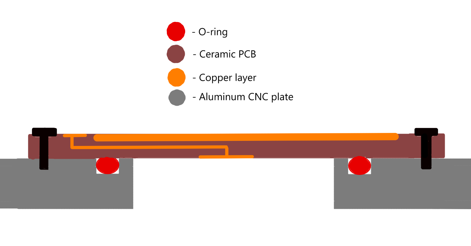 |
|---|
| Figure 9: Ceramic PCB electrical feedthough sealing with legend. The red O-ring can be made out of Buna-N or Viton, but it can also be made of hollow copper tubing given that the PCB will rarely be taken out of its socket, yielding close to zero outgassing and much better sealing quality overall |
Vias won't be used, as they can provide leak paths for air to flow through, contaminating the vacuum. A pair of O-ring seals will be placed around the connections, between the CNC panel and the ceramic PCB, sealed with silicone vacuum grease.
At the same time, all electrical cables inside the vacuum have to be insulated with teflon tubing or kapton film, both ideal UHV and HV grade polymers that have extremely low outgassing rates. PCBs will be avoided inside the vacuum at all costs, given that resin FR4 boards can contaminate the vacuum and create a pressure floor above target. Moreover, trapped air pockets inside the component housings can burts and damage the board. Overheating of ICs would also represent an important caveat.
¶ Mechanical considerations
Many greases used in mechanical applications to lube bearings and gears have vapor pressures set too high for vacuum use, outgassing water vapor as well as hydrocarbon molecules, contaminating the chamber.
Many vacuum-grade greases contain silicon, which is fatal for metal-on-metal mechanisms (steel ball bearings with metal casings; metal gears), wearing out fast and ultimately failing. Silicon greases are typically used only for sealing O-rings and clamps in vacuum systems.
Low vapor pressure high-end greases are highly expensive, engineered specifically for vacuum. Because of this reason, fully ceramic bearings will be implemented (ceramic balls + housing).
Ceramic bearings are excellent for vacuum use, to the point where they don't require lubrication, possesing high wear and thermal resistance. Moreover, PTFE (teflon) linear bearing slides are also acceptable for vacuum use, replacing metal bearing ones.
Gearboxes as well as any gear metal-on-metal systems will be avoided, transmission on belt being the norm for this project. Plastic gears will not be implented, as their outgassing rate, high backlash as well as low durability don't fulfill the purpose of this project, as both high film and 3D print part quality are desired, both requiring mechanical reliablity.
Because of this reason, stepper motors will be the only type of motor used (nema stepper motors), containing only two metal bearings on top and bottom (which will be replaced with ceramic ones) and no gears (unlike servo and DC motors). Direct (or belt) coupling will therefore be the only methods of coupling used, bypassing gears entirely.
metal O-rings will be made out of smooth hollow annealed copper wire which will be used to seal nearly permanent bolt connections that rarely need replacing or opening, likely structural components such as the electrical connection feedthrough, the chamber walls etc. These metal O-rings suffer from permanent plastic deformation, ulike Viton rings, limiting the number of times they can be used.
¶ Filament considerations in vacuum
In deep vacuum, most materials experience a certain degree of outgassing, given by the time taken for inner organic volatile gases to desorb and diffuse though the material walls. Most common outgas gases are H2O, H2, N2 or O2. H2O typically represents 80% of the total outgas quantity, depending on the specific atmospheric conditions in which the material has absorbed water form the atmosphere. Materials such as metals also experience outgassing, water vapor traveling through the metal walls and out into the vacuum chamber. Filaments and components are usually degassed and baked for couple days prior to usage, removing most of the absorbed gas.
Furthermore, as one study puts it, “Outgassing rates, for example, largely determine a material’s suitability for vacuum or space applications. Perhaps more importantly, the suitability of a material for applications in gas sensing, for gas filters, or for gas storage strongly depends on the ability of the material to uptake or desorb gas.”
Filament outgassing represents a great cause of concern for our project, given that if filament is not properly deep vacuum dried before use, it would foam and basically explode when molten at 250 C inside the printing chamber. Therefore, it's important we take into consideration proper filament drying techniques in vacuum, as well as specific filament differences that help us choose the best polymer for vacuum use.
Filaments that can be considered vacuum grade have low outgassing and diffusion coefficients, meaning that they release less gas when put under high vacuum. Vacuum grade filaments should also allow for gas desorption in an acceptable amount of time, vacuum components being typically degassed and baked before use.
ABS has a lower diffusion rate when compared to PLA and PETG, sitting at around 8.1 × 10⁻⁸ cm2/s and 8.3 × 10⁻⁸ cm2/s, respectively. Water diffusion through ABS is similar to typical elastomer seals used in high-vacuum systems (viton o rings or buna-N), making it a suitable polymer that can be used in vacuum systems, especially in our project. Amorphous materials (such as plastics and glass), have a glass transition temperature, which once passed can alter structural strength, making them soft and malleable. ABS glass transition temperature sits between 105-115 C. ASA, a close polymer in chemical composition to ABS, has a slightly lower glass transition phase, a minimum of about 100 C. The same aforementioned article suggests that, ABS baked at 103 C-just under the glass transition temperature-in high vacuum for about 3 days removes almost all gas from the filament. Outgas rates depends on gas diffusion path through the inner walls of the material, which makes it easy for filament outgassing, given its small thickness.
| |
|
| Figure 10: mass variation during vacuum drying of an ABS sample- rectangular cuboid of dimensions of 6.0 mm × 48.0 mm × 24.9 mm and a mass of approximately 6.5 grams (before loading with gas) |
|---|
ASA is typically considered a better alternative to ABS, having better mechanical and chemical properties, as well as generally higher resistance to environmental factors that would otherwise degrade in time most polymers. Its superior diffusion coefficient allows for higher resistance to environmental factors that would otherwise degrade other polymers, having higher moisture resistance and less gas retention, as well as better UV resistance and less release of toxic fumes during 3D-printing (such as styrene when printing with ABS) amongst others. Water reabsorption of ABS and ASA filaments sits between 0.2-0.6% by weight, depending on time of exposure, and the humidity level of the atmosphere in which the filament spools have been deposited. Therefore, it should be tested if ASA yields better results in near vacuum printing when compared to ABS.
Storing and vacuum drying filament spools in controlled chambers before use could also drastically improve print quality, not just film deposition, by removing virtually all moisture from the filament. Therefore, a chamber in which filament is stored would have to be build next to the printer, bypassing the main vacuum pump to it. Also, a heater would have to be mounted inside so that filament can be baked and vacuum dried before use.
In normal printing mode, pressure inside the chamber will be kept slightly higher than in film deposition mode, given that filament is heated beyond melting temperature during printing, resulting in higher outgas rates and possible foaming in high vacuum. During film deposition, air inside the chamber will be pumped down, the temperature of the plastic printed substrate remaining lower than bed temperature, and thus lower than the temperature at which filament had been baked before use, keeping outgassing at a minimum.
¶ project timeline
- The first functional, stationary prototype will be tested inside a nitrogen atmosphere, at atmospheric pressure. The prototype will have the ability to plate thin, rough metal surfaces (probably aluminum given its low melting point and affordability), with reduced magnetic confinement, cheap magnetron and air/fluid cooling. the substrate will likely be negatively biased metal.
- 3D printing will be tested inside a vacuum, evaluating styrene production rate and volume, working temperature, layer cooling techniques, nozzle temperature PID tuning, bed adhesion, filament drying time and conditions as well as the working pressure at which printing will be done
- vacuum sealing techniques will also be evaluated inside a real vacuum, electrical feedthroughs, mechanical feedthroughs, material wall strength etc
- metal plating inside a vacuum will also be tested, gas flushing, liquid cooling and magnetic confinement etc.
- More performant magnetron will be used and evaluated.
- bed heating pid will also be tested inside a vacuum
- linear closed loop stepper prototype will be tested and a printer will be bought, at which time a 3d printer vacuum chamber will also be tested to assess strength and outgassing from the walls.
- other mechanical components will be introduced inside the printer, testing the vacuum once again and evaluating reliability.
- Printing and tuning will be adjusted inside the vacuum, testing different speeds and working pressures, evaluating temperature rise inside the chamber so that thermal runway can be avoided.
- the metal plating tool changer will be installed inside, allowing the printer to swtich between the two. More tuning more evaluation...