


¶ Description
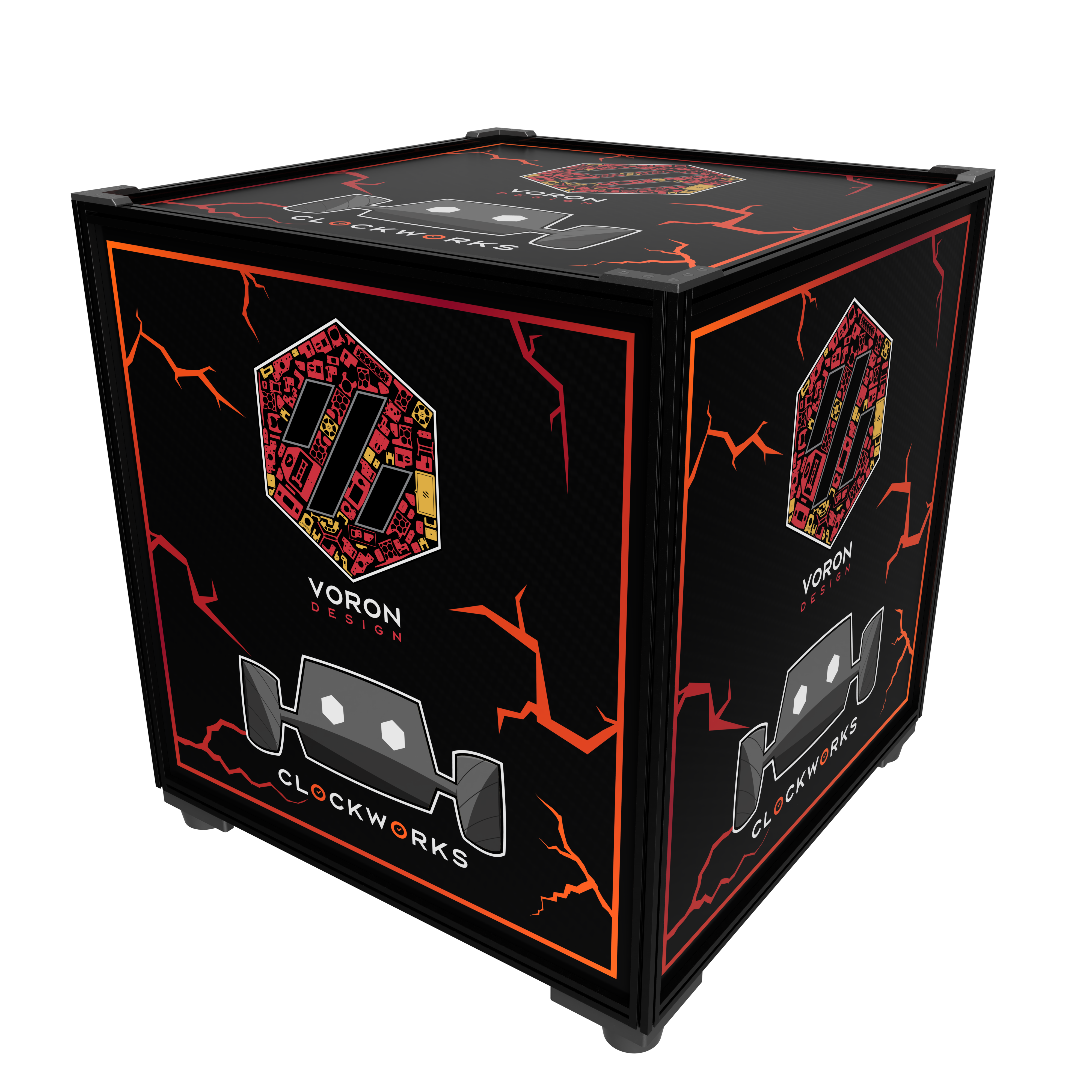
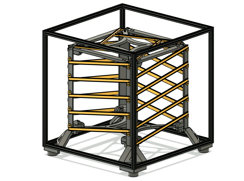
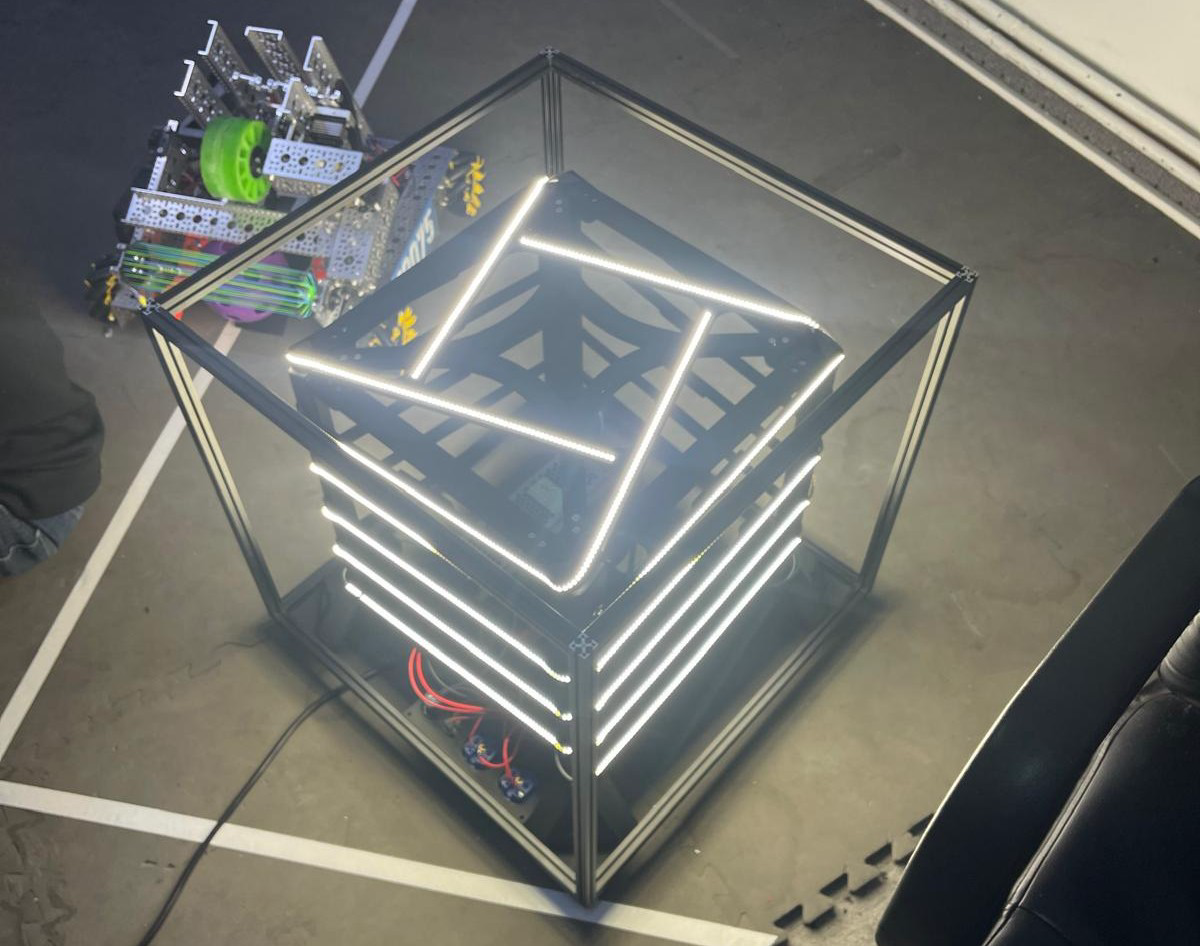
Boron (Box-Voron) is an open-source light cube that can be built for relatively cheap. The sides graphics are interchangeable and allow for quick reconfiguration by unscrewing the top of the frame. It allows us to display a large logo on a structure very similar to Voron printers.
The project is licensed under GNU General Public License Version 3. This means, among others, that distributing either STL, printed parts or assemblies containing Boron, you must also make the modified CAD available to users.
The design is built so that minimal electronics and soldering work is required. A 10-meter LED strip is cut into 4 equal sections and is wrapped around the cube's guide channels. Each strip's end arrives at the top of the cube, where it transitions to the top face. The electronics operate at 24V to allow the Shelly controller to switch more power for the same current.
The bottom of the cube contains two output wall sockets to aid with wiring. (Maybe chain more Borons?).
CAD files, STL files and firmware can be found in the Github repository.
 |
 |
|---|
 |
 |
 |
 |
|---|
¶ Graphics panels
The side panels should follow this specification:
- Theoretical visible area: 470mm x 470mm
- Physical panel size: 477mm x 477mm
- Usable visible area: 467mm x 467mm
- Hidden border background: 5mm on each side of the usable visible area
The graphics elements should cover the entire usable visible area, but the background must continue up to the edges of the panel.
The panel is phisically slightly smaller than the available area to acount for manufacturing inaccuracies.
Ask your local supplier of plexiglass or PC panels about what transparency they offer. You want semitransparent, white panels. Fully transparent panels will allow you to see right trough the ink and completely opaque (like PVC) will let no light trough.
¶ Parts List & Sourcing Guide
| Category | Part | Quantity | Notes | Distributor |
|---|---|---|---|---|
| Frame | MakerbeamXL 500mm beam | 4 | Order 12x 500mm MakerbeamXL beams and also add 8x Cut&Tap services to the cart. Specify in the description that 8 of the 500mm beams need to be cut to 470mm | Beams Cut&Tap |
| MakerbeamXL 470mm beam | 8 | |||
| ABS/ASA Filament | 3kg | The prints are a bit heavy on filament usage. The recommended quantity takes into account possible print failures for the very big parts that are susceptible to warp. The cube will put out about 20k lumens and consume upwards of 240W, therefore it might heat up a bit. ABS or ASA is strongly recommended to withstand the heat. Source from your favourite local european filament factory. |
Prusa RepRapMania |
|
| Electronics | Shelly Plus RGBW PM | 1 | EMAG | |
| Wall Socket Gewiss GW 62393 |
2 | EMAG | ||
| 10k Potentiometer with 22mm bore Tayieei LA42DWG-22 |
1 | EMAG Aliespress |
||
| LED Strip (10m) | 10m | At most 10A/240W, minimum 10m Neutral white is preferred |
TME.EU EMAG |
|
| Wago 221 415 5-wire | 7 | TME.EU EMAG |
||
| IEC C13 Socket | 1 | TME.EU EAMG |
||
| IEC C13 Cable with 90* bend | 1 | TME.EU EMAG |
||
| 24V PSU Meanwell UHP-350-24 |
1 | TME.EU | ||
| 20AWG or 0.5mm2 multistrand silicone insulated wire | 8m | Get at least 2 colors | TME.EU | |
| Fasteners | M3 Voron brass inserts | 54 | 6x for utility panel 8x for top led 40x for LED channels |
CNC Kitchen |
| M3 BHCS (DIN 7380) 8mm | 56 | 40x for LED channels 16x for frame |
Screwsandmore.de | |
| M3 BHCS (DIN 7380) 16mm | 30 | 2x for utility panel 12x for feet 16x for internal feet |
||
| M3 BHCS (DIN 7380) 10mm | 10 | 6x for PSU mount 4x for shelly mount |
||
| M3 BHCS (DIN 7380) 40mm | 3 | 3x for utility panel | ||
| M3 FHCS (DIN 7991) 8mm | 34(114*) | 8x for top led 10x for utility panel 16x for top corners 80x for modular channels |
Screwsandmore.de | |
| M3 FHCS (DIN 7991) 4mm | 4 | 4x for top corners This part is aesthetic and optional |
||
| M4 SHCS (DIN 912) 16mm | 64 | 64x (8 per corner, 8 corners) | Screwsandmore.de | |
| Makerbeam T-Nut XL | 43 | 16x for internal feet 8x for feet 3x for utility panel |
Makerbeam | |
| Panels | Painted polycarbonate sheets 477mm x 477mm 3mm thick |
5 | Use your local supplier of panels. Paint them with your logo or graphics. | headprint.ro |
*For M3 FHCS (DIN 7991) 8mm screws, normally 34 are required. If you want to go the Alternate (modular) LED channels, 80 more screws will be required to assemble channels.
¶ Printing
Most of the parts fit on a 3003 printer, but the bottom and top crossbars should be printed on a 3503 machine.
Use 3-4 perimeters for all parts and 25% gyroid infill. A thicker line width for infill will speed up the print a lot and add extra strangth.
For the external and internal feet, we recommend at least 5 perimeters to ensure these will not creep over time.
All parts are already oriented in the best position for printing.
| Category | File | Amount | Notes |
|---|---|---|---|
| Structure | Foot.stl |
4 | 5+ perimeters. |
Stacking Foot.stl |
4 | If planning to stack multiple borons, this alternative foot designs allows for cubes to be rigidly placed at 25* angle offset and both on the ground. If printing this variant, do not print the regular Foot.stl. |
|
InternalFoot.stl |
4 | Add supports for the steep overhanging area. 5+ perimeters. |
|
Post.stl |
4 | 3503 print area required. | |
TopCrossbar.stl |
1 | ||
BottomCrossbar.stl |
1 | ||
Corner.stl |
8 | ||
TopBar.stl |
4 | ||
TopCorner.stl |
4 | ||
| Electronics | ShellyBase.stl |
1 | |
ShellyStrap.stl |
1 | ||
UtilityPanel.stl |
1 | ||
WagoHolder.stl |
1 | ||
UHP-350-Mount.stl |
1 | ||
| LED Channels | LEDChannelTop.stl |
1 | 3503 print area required. |
LEDChannel.stl |
20 | 3503 print area required. If you want to print this on a smaller printer, we have an option below. | |
| Alternate LED Channels | HalfChannel.stl |
40 | If you do not want to print the LEDChannel file because it takes a lot of bed space, print these two files instead. Two HalfChannel and one CenterChannel are assembled together with 4x 8mm M3 FHCS to yield an equivalent part. If printing the regular channels, do not print this. |
CenterChannel.stl |
20 |
Many holes for M3 screws are dimensioned at 4.7mm. Insert heatset threaded inserts into these holes with a soldering iron. Perfect centering is not crucial because the design makes use of slots in many places where heat inserts are placed. In total, you should use 54 inserts.
¶ Flashing ESPHome on the Shelly controller
For this step, you will need a standard USB-UART converter. CH340 or FT232 modules work perfectly. A computer with linux environment is strongly recommended.
Flash the firmware onto the Shelly controller before assembling the electronics. Doing so after will complicate the setup a lot.
¶ Connecting UART wires
A breadboard can be very useful for making connections because we will have to connect GND to two different places. The back of the shelly contains a few pins for flashing. The slots for pins are very small, therefore use wires from inside a CAT5A network cable that have solid copper cores.
Ensure that your UART adapter is set to work at 3.3v levels, as the ESP inside shelly does not tolerate 5v signaling.
Connect the UART adapter to the shelly as follows:
| Shelly | UART Adapter | Diagram |
|---|---|---|
| U0TXD | RX | 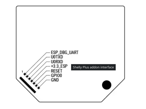 |
| U0RXD | TX | |
| GND | GND | |
| GPIO0 | GND | |
| +3.3_ESP | +3.3v |
¶ Flashing
Power on the assembly by connecting the USB adapter to your linux computer, and take note of the serial port:
# Show all serial ports that are not system ports
ls  /dev/* | grep 'tty[^S0-9]'
Install the ESPHome toolkit:
# Arch linux
sudo pacman -S esphome

# Debian, Ubuntu, others
sudo pip install wheel esphome --break-system-packages

# Test your installation
esphome --version
Clone the repository with ESPHome config files and start flashing:
# Clone the repo
git clone https://github.com/TeamClockworks-RO108/Boron.git
cd Boron/firmware

# If you wish to have network control over boron's state, edit the secets.yaml file
# Replace wifi1_ssid and wifi1_password with your network credentials.
# You can configure up to 4 wifi networks.
vim secrets.yaml

# Flash. Replace /dev/tty<port> with your serial port obtained above.
esphome run boron-basic.yaml --device /dev/tty<port>
¶ Assembly
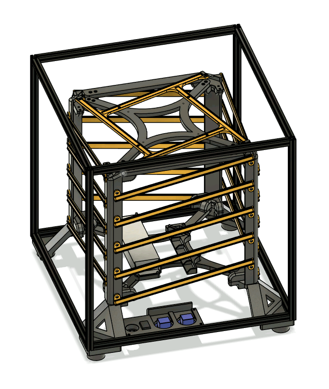
It's advised to have the CAD file open during the assembly process. We have included many photos and highlights in this guide, but it's always useful to be able to check details with the CAD.
We will assemble the frame first, together with its internal and external feet and then build the inner LED cube.
At the end, we will combine both and wire up the electronics.
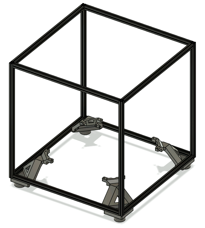
¶ Frame
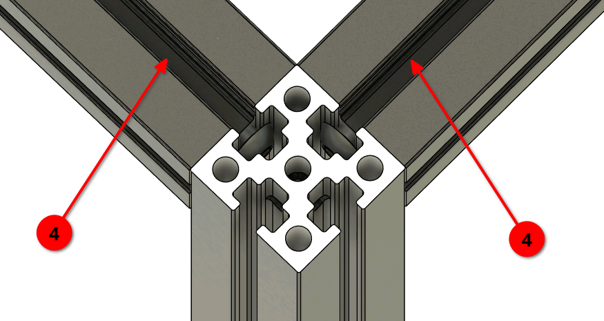
Use the extrusion drill guide to drill access holes for blind joints into all of the 500mm extrusions (4). You should drill 4 holes for each extrusion (a cross at each end). Use a 3mm drill bit.
In total, 16 holes need to be drilled (4 beams x 2 ends x 2 holes).
Assemble the frame using 16x 8mm M3 BHCS. Use a flat surface to ensure the frame will be perfectly square.
When assembling the bttom face, preload the following Makerbeam XL Nuts:
- 2 nuts on each extrusion on the bottom side
- 4 nuts on each extrusion on the inside of the cube. On one side (that will be the back side) preload 7 nuts.
- 4 nuts on each extrusion on the top of the cube, all on the top side.
A total of 43 nuts must be preloaded.
 |
 |
|---|
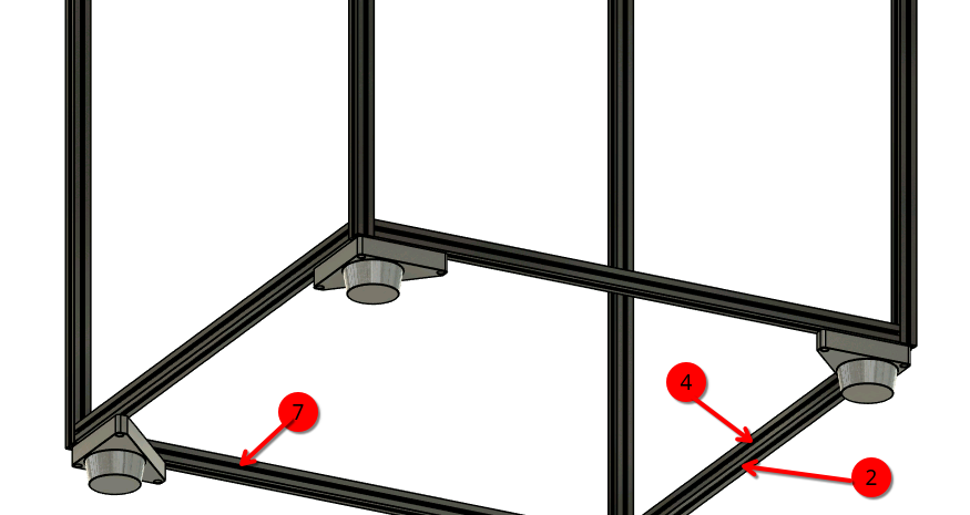
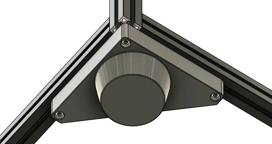
Mount the external feet using 3x 16mm M3 BHCS and the internal feet using 4x 16mm M3 BHCS.
The middle screw of the external foot threads into the extrusion.
Use the preloaded nuts in the earlier steps.
 |
 |
|---|
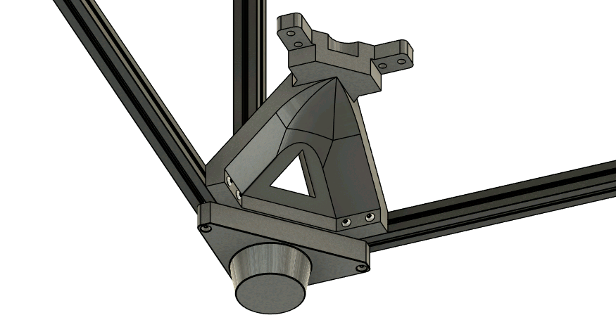
If using the stacking feet, assemble them as usual instead of the regular feet. The channel inside the foot helps align with the frame of the botton cube.
 |
|---|
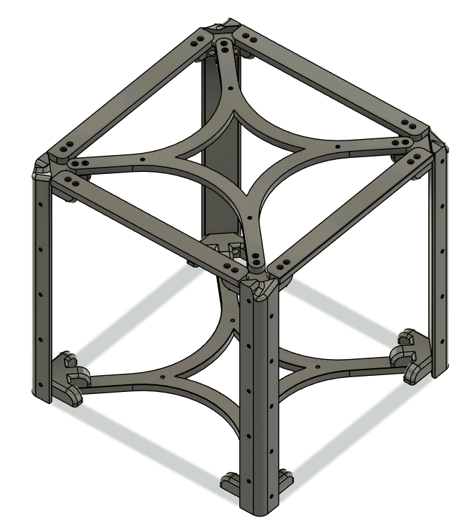
¶ Final assembled frame
 |
|---|
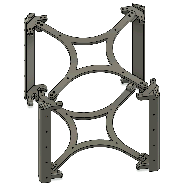
¶ LED Structure
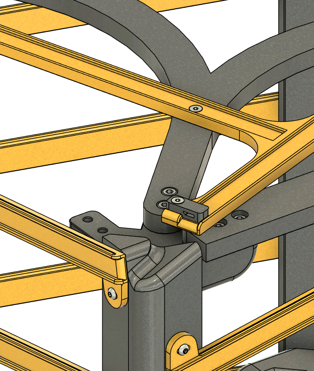
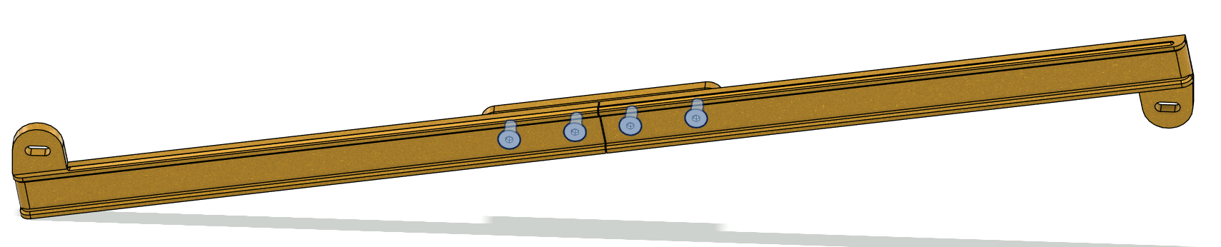
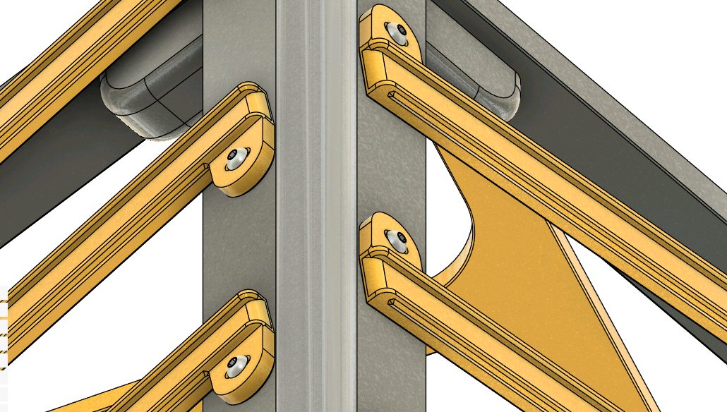
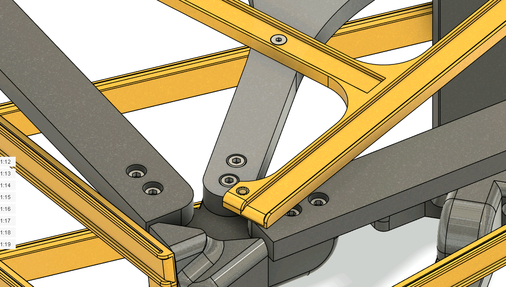
Assemble the main LED structure using 32x 16mm M4 SHCS screws. Connect the brackets to the main pillars and use the two crosses to fasten the 4 corners.
The two crosses are not identical! The top cross contains heated inserts on the upper side that will later be used to mount the top face LED channels. Install this part on the same side with the filleted pillars. The bottom cross has only 4 regular holes for mounting of the PSU and electronics.
Afterwards, install the rigity supports at the top using 16x 16mm M4 SHCS screws. These beams help stabilize our build.
 |
 |
 |
|---|
¶ Alternative LED Channels
If you opted for the alternative channels (3 piece part instead of single piece), then it is time to assemble them now. Join two halved with the center piece using 4x 8mm M3 FHCS. Repeat this step 20 times.
 |
|---|
¶ LED Channels
Install the 20 lateral LED channels. Mount them with 40x 8mm M3 BHCS screws. The channels have slots that allow good mounting even if the frame is not prefectly square.
Afterwards, mount the top face LED channel using 4x 8mm M3 FHCS. These screws will go in the heatset inserts inside the top cross.
 |
 |
|---|
The LED structure is now ready for mounting inside the main frame. Use 16x 16mm M4 SHCS.
 |
 |
|---|
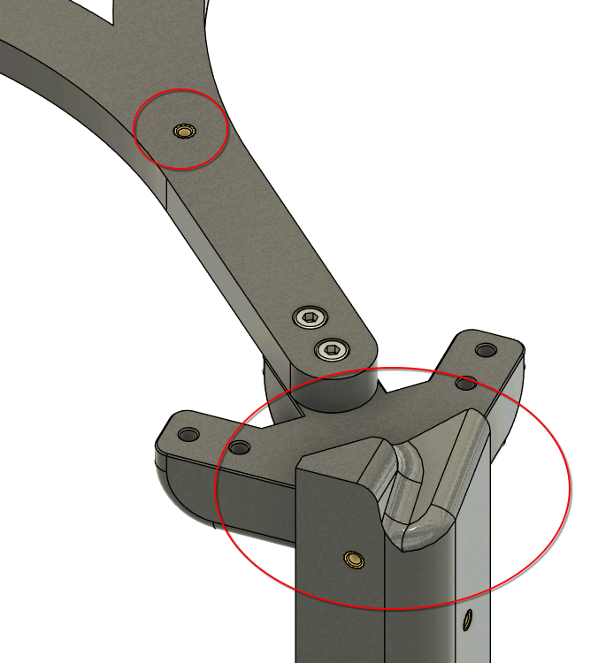
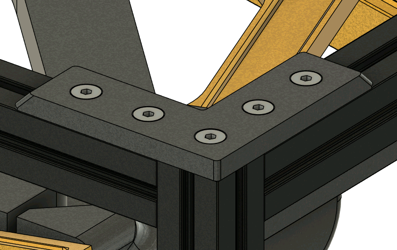
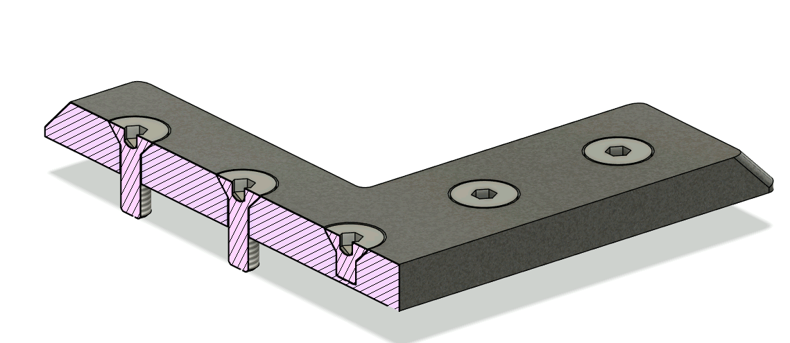
¶ Top corners
Secure the top corners using 4x 8mm M3 FHCS (for each corner) and the MakerbeamXL nuts preloaded earlier. The 4mm M3 FHCS screws only into the plastic part and is decorative.
 |
 |
|---|
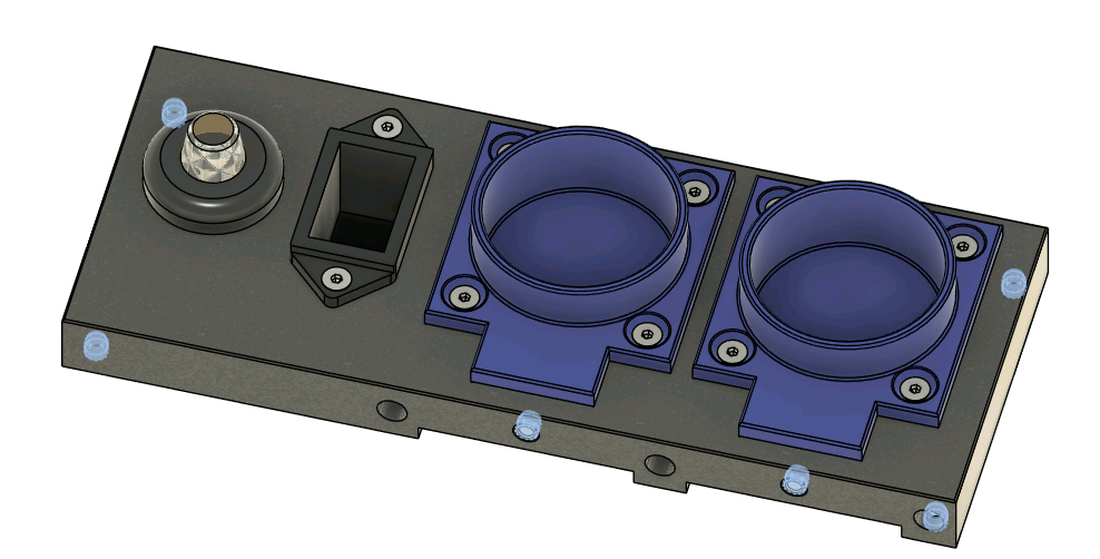
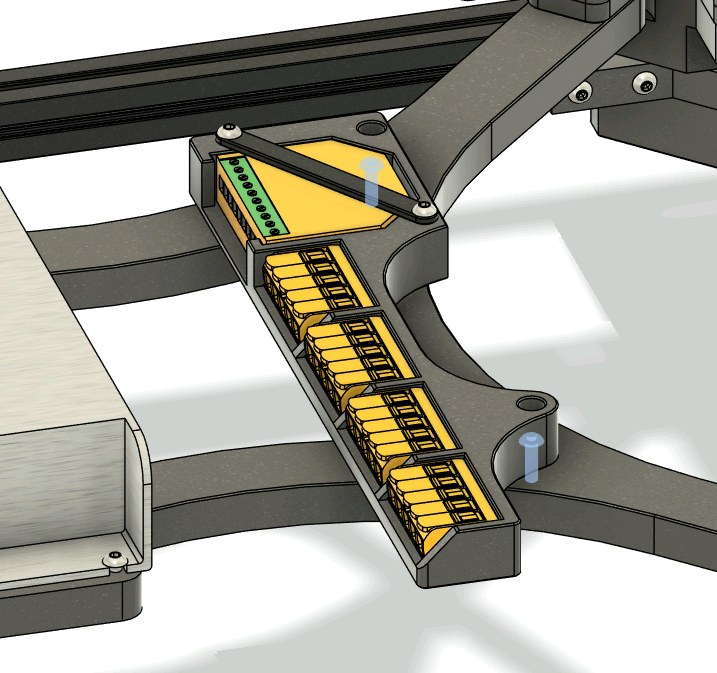
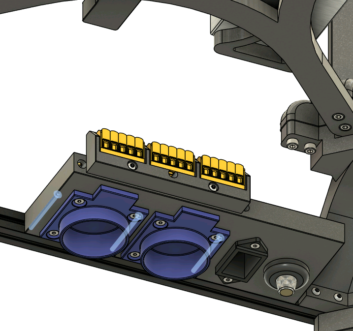
¶ Electronics
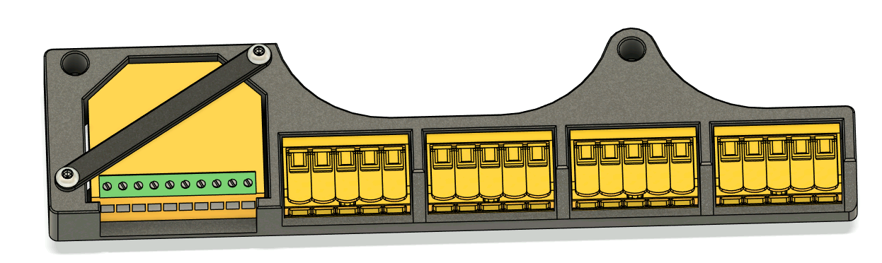
Start by inserting the 6 heat inserts. Then, fix in place the sockets and the C13 power plug using 10x 10mm M3 FHCS.
To install the potentiometer, unscrew the included nut and put it trough the hole. Then, screw back the included plastic nut.
Secure the WAGO holder into the utility panel body using 2x 16mm M3 BHCS. To make the WAGO connectors stay in place, we can use Cyanoacrylate glue or hot glue.
 |
 |
|---|
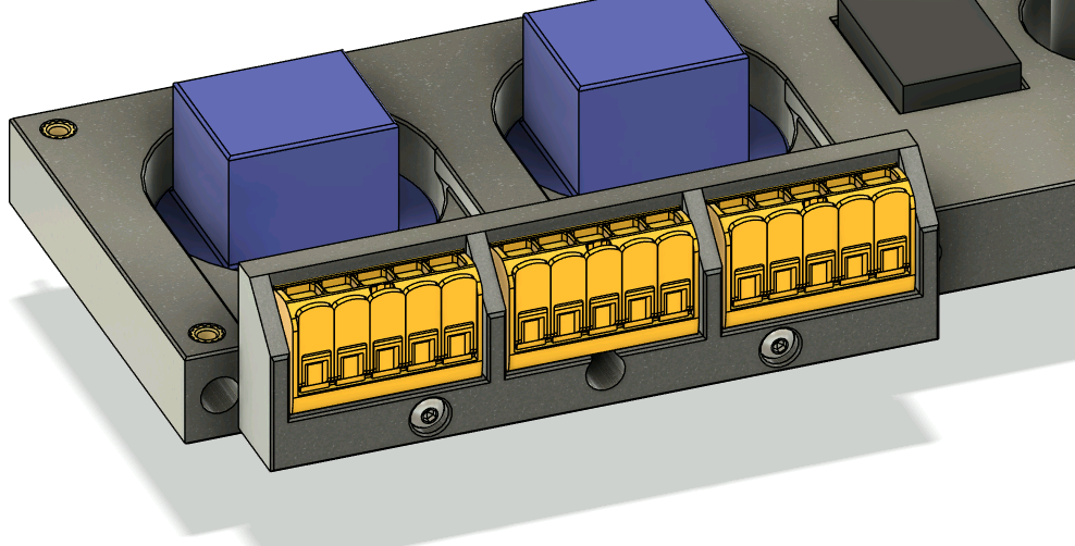
Assemble the Shelly holder by sliding the shelly relay inside and securing it into place with its small bracket and 2x 10mm M3 BHCS.
Use the same glue technique as above to install the 4 WAGO connectors.
 |
|---|
¶ Wiring
To properly program the elctronics, we will assemble and test the wiring outside the cube!
The wires between individual components nearby should be small. Eyeball each length to your preference. Wire lengths between different places inside the cube should be:
- Utility panel (potentiometer) to shelly circuit - 300mm
- Utility panel to PSU (AC side) - 130mm
- PSU (DC side) to shelly circuit - 270mm
- Shelly circuit to LED strip start - 360mm
All screw terminal connections (on the shelly relay or power sockets) should use crimped ferrules to prevent accidental disconnections.
Wires connected to wago terminals do not ferrules, but ensure that about 8-11mm of wire length is unsheathed.
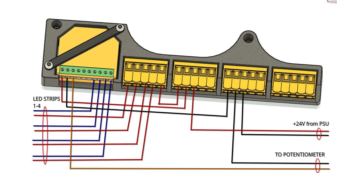
¶ Utility panel
When wiring the utility panel, take extra care to ensure that the neutral line (yellow, often found as yellow-green) does not mix with the two power lines.
The potentiometer has three connection points: two ends and one center tap. We will wire one single end and the center tap, wires which will go to the shelly circuit. Dimension the wire accordingly.
 |
|---|
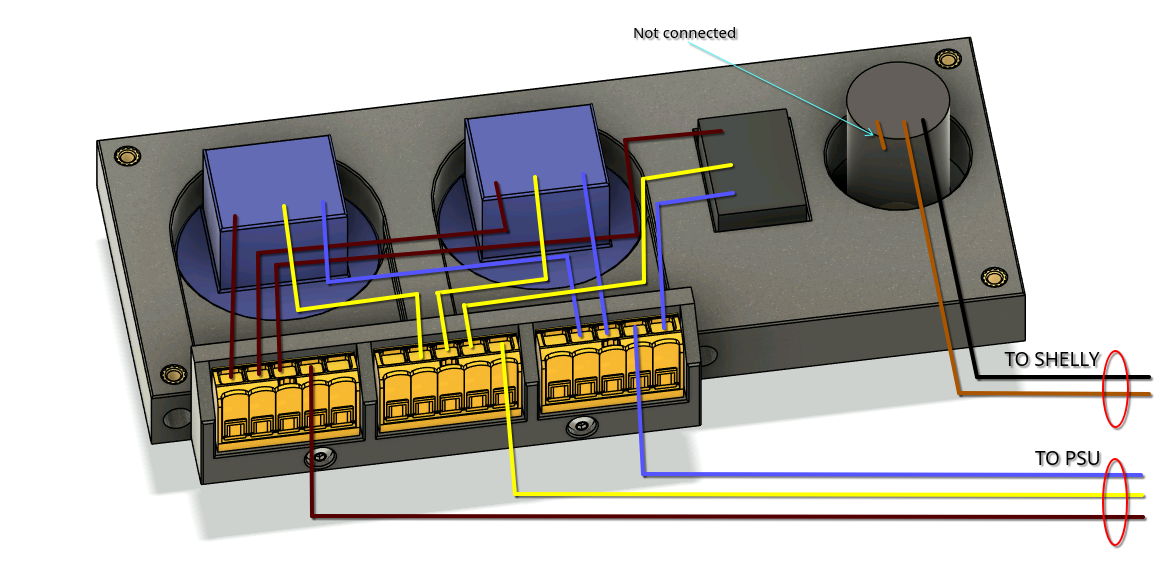
¶ Shelly circuit
Follow the diagram below to wire the shelly circuit.
 |
|---|
¶ PSU
Connect the power wires coming from the utility panel to the PSU's AC side. Take extra care to find the right connector for the neutral wire.
Connect the +24V wires from shelly circuit to the PSU's DC side, respecting polarity.
¶ LED Strips
Cut your 10m strip into 4 equal 2.5m sections and solder one end of each strip to the LED wires coming from the shelly circuit.
¶ Power on & Check circuit.
Before connecting power to the assembly,
ENSUREthat all AC connections are properly done and there are no exposed wires. There should be no connection between the AC circuit and DC circuitEXCEPTtrough the PSU itself.
The DC section is relatively safe to touch, but please take care. DoNOTtouch the AC side of the circuit inANYcircumstance.
Repeat: Do
NOTtouch the AC side of the circuit inANYcircumstance.
Plug in the power outlet. You should see a green light on the shelly controller. By turning the potentiometer, you should be able to adjust the intensity of the LED strips. All LED strips should light up at the same intensity.
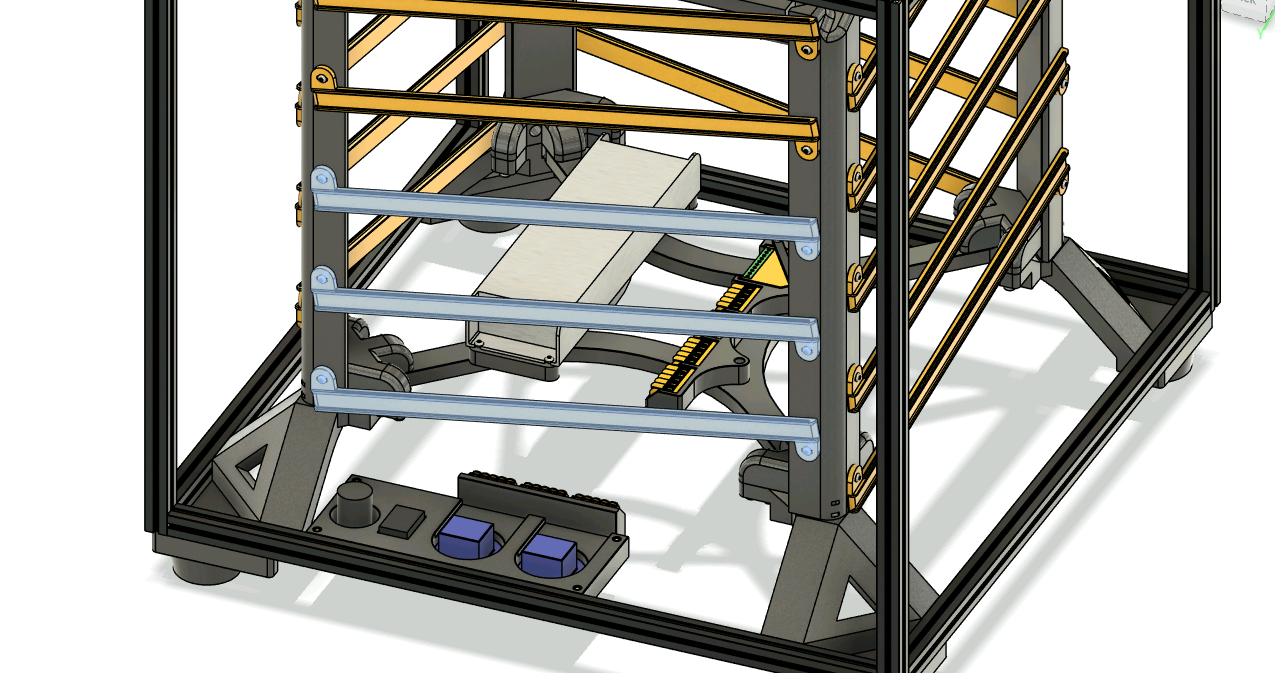
¶ Mount electronics inside the cube
Take off the bottom three LED supports from the back of of the cube. The back is the side where we preloaded 3 more (total 7) channel nuts in the bottom extrusion. We will be using these nuts to mount the utility panel we just wired.
 |
|---|
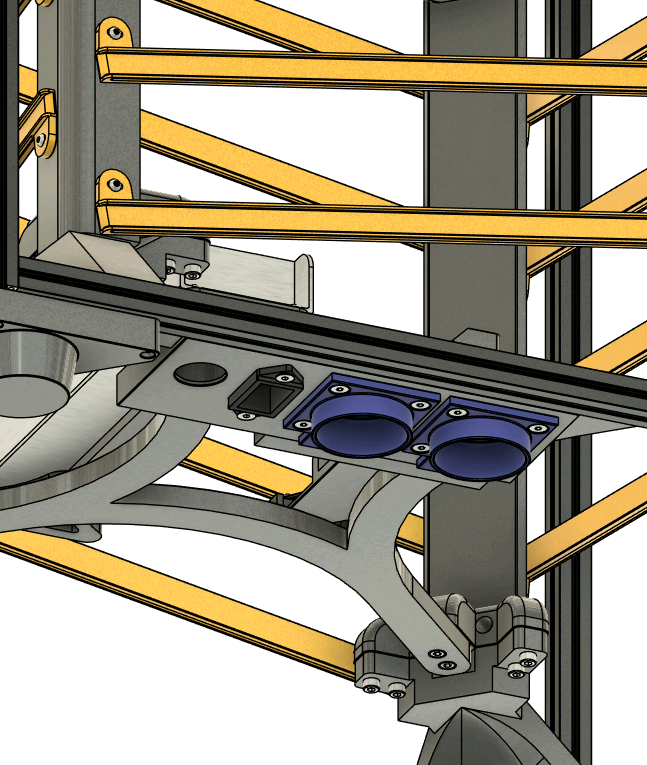
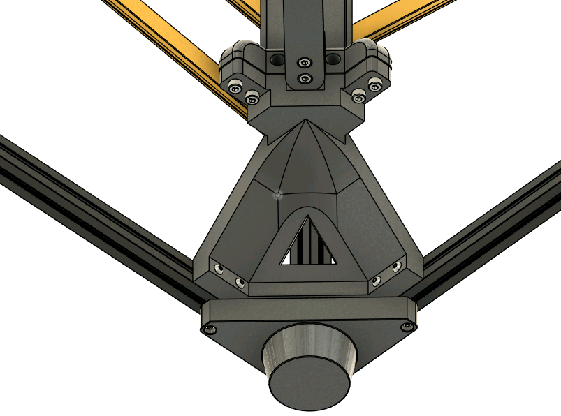
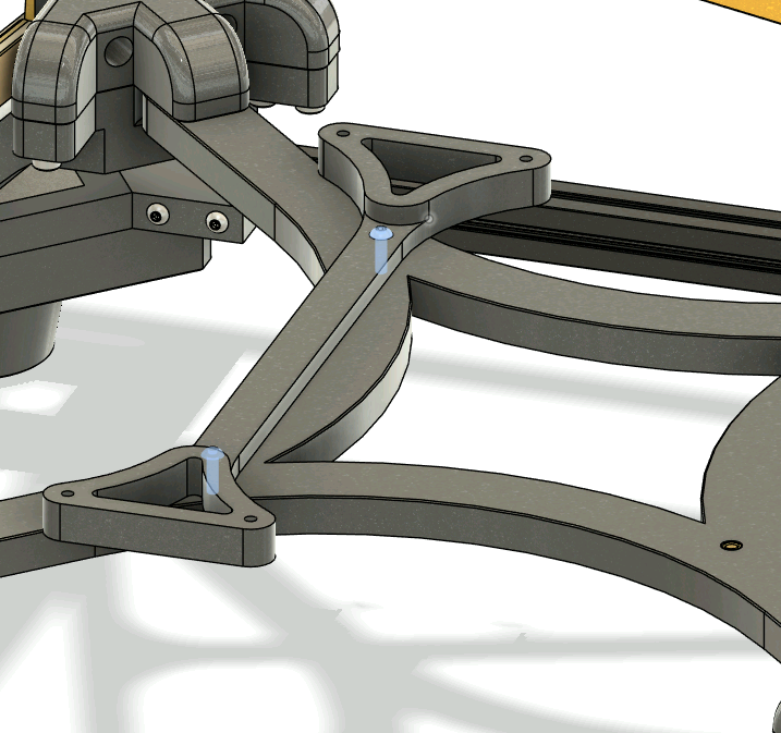
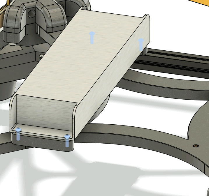
It's time to add the electronics:
- Mount the UHP-350-Mount to the bottom cross using 2x 10mm M3 FHCS
- Mount the UHP-350 to its mount using 4x 10mm M3 FHCS
- Secure the shelly carrier to the bottom cross using 2x 10mm M3 FHCS
- Secure the utility panel to the back extrusion using 3x 40mm M3 FHCS. Use the three extra preloaded nuts.
 |
 |
 |
 |
|---|
Install back the three LED supports you just took off to aid in electronics mounting
 |
|---|
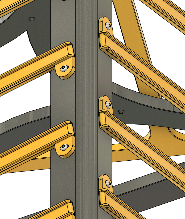
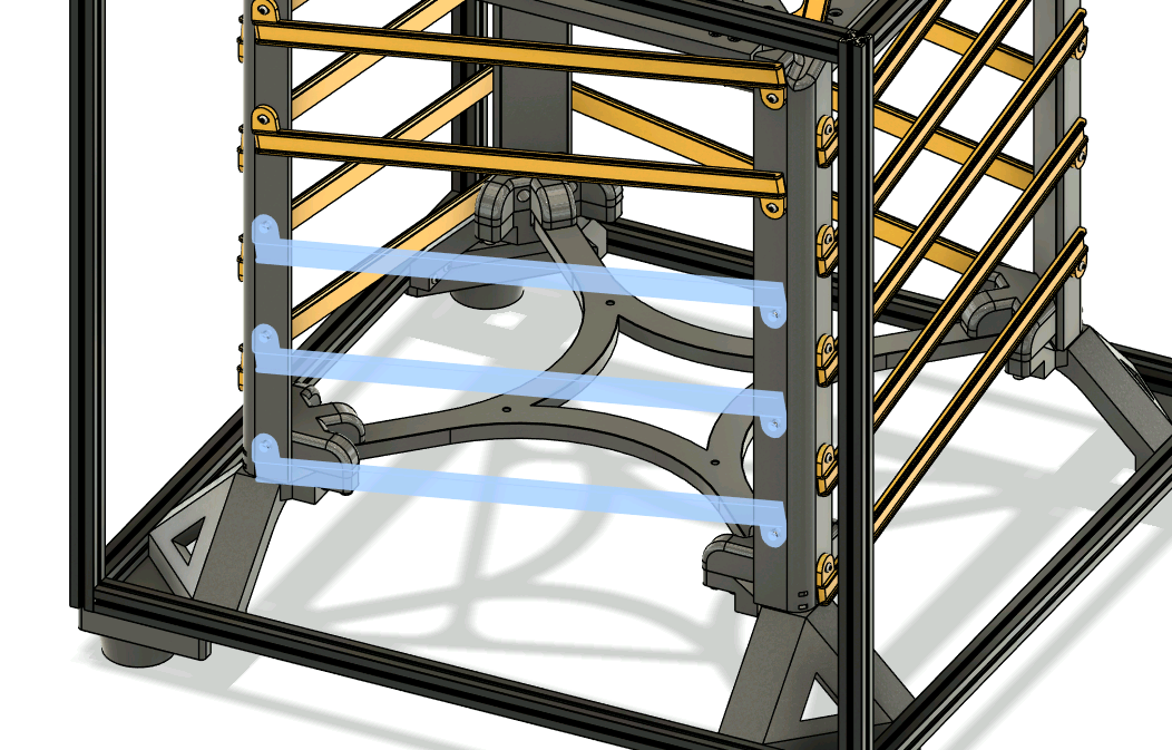
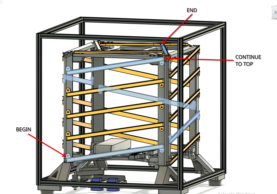
¶ Wrap the LED strips around the cube
Take each LED strip and direct one towards each vertical post. We will wrap each strip on the track that starts at the bottom of each post. After 5 segments, you will arrive at a top of a vertical post, where we will continue towards the top support track.
This is how one of the strips wrap. Repeat this pattern for all 4.
At the bottom of the post there is a ziptie loop to help you keep the cables in place.
 |
|---|
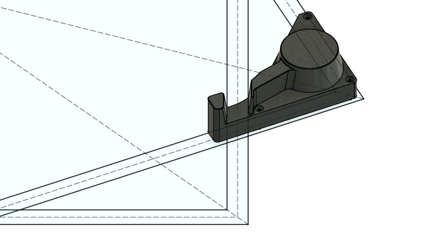
If you are having trouble keeping the strip in place at the top corners, install one of the strip clips using an 8mm M3 FHCS screw.
This screw threads inside a brass insert, so don't forget to install that too.
 |
|---|
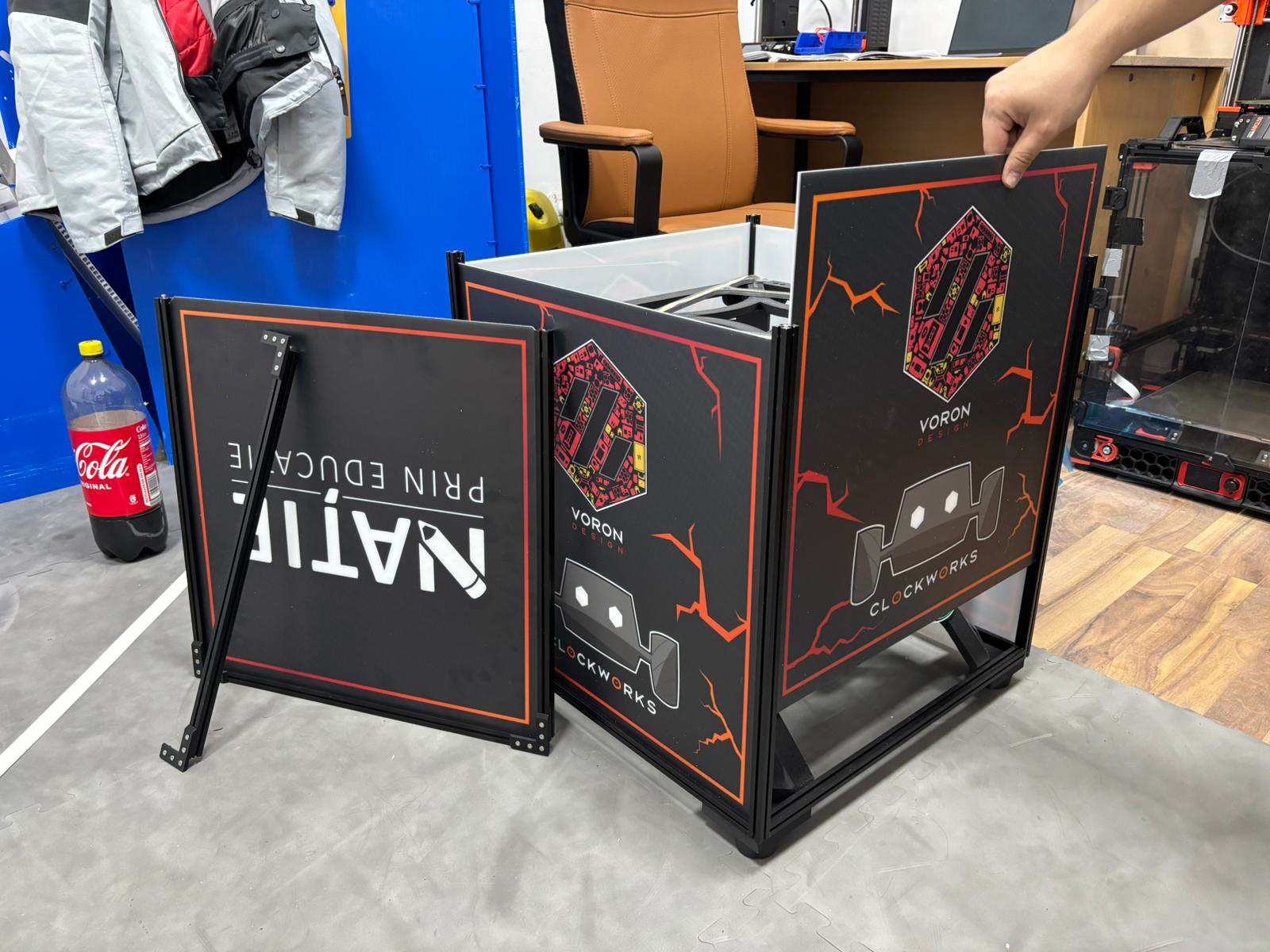
¶ Panel mounting
Loosen the 8 buried screws at the top of the vertical extrusions and take the top square out. The top corner pieces will keep the square in one piece. Unfasten two corners (total 4 screws) to break the square into an U and an I.
Install the 4 side panels and the top panel (the chamfered one).
Reassemble the U and I, but do not tighten the corners fully. Place the square in the frame and tighten everything.
 |
|---|
¶ You are done
Congratz! Shoot us a mail at contact@teamclockworks.ro with photos of your build! We'd love to do a gallery here and issue you a serial number!
¶ Gallery
 |
|
|---|---|
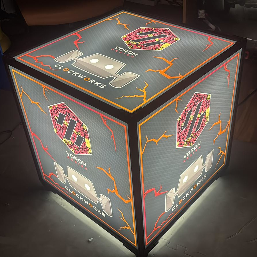
| The first Boron ever built! It puts out roughly 18000 lumens without the panels installed. At 24.6V we are seeing a current draw of 6A, so we have a lot of headroom on the UHP PSU. We are thinking about adding some TypeC PD chargers for the many small projects we have at our stand.   |
| The second boron will feature another option for the power supply (HDR-150-24) and options for printing the main posts in two pieces. Stay tuned! |
|---|