


![]()
¶ Description
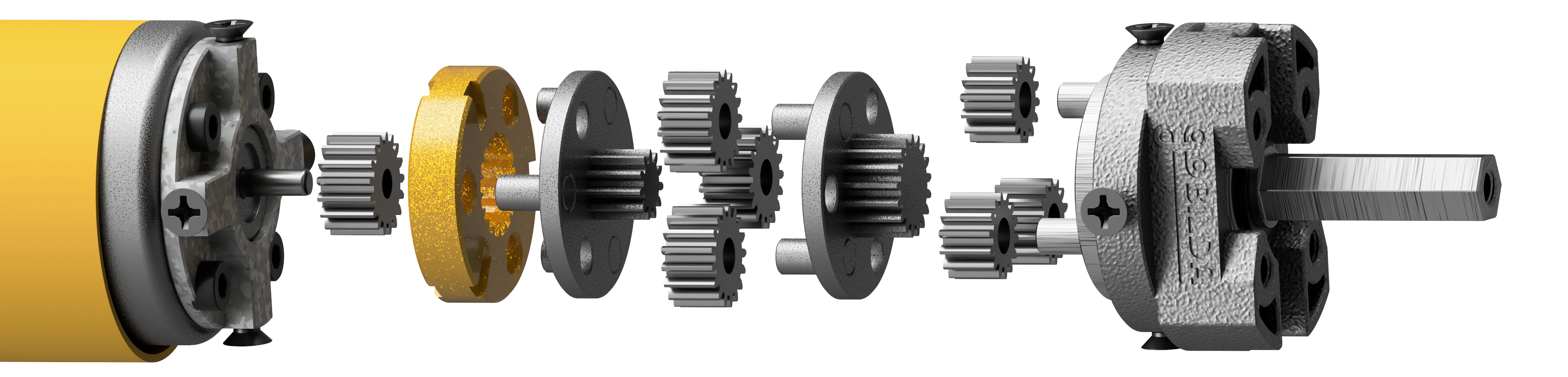
Starkiller is a 3D printed file that allows a Gobilda Yellow Jacket 84 RPM motor to transform to any of the following speeds: 6000 RPM, 1620 RPM, 1150 RPM, 435 RPM, 312 RPM. It works by replacing parts of the planetary gearbox with fixed stages.
The system also fits any other planetary gearbox from gobilda (not neccessarily the 84 RPM one) but we have selected the 84 RPM motor as the main focus because its planetary configuration can produce most of the other options.
The CAD is licensed under GNU General Public License Version 3. This means, among others, that distributing either STL, printed parts or assemblies containing Starkiller, you must also make the modified CAD available to users.
The repository for this project can be found here.
 |
|---|
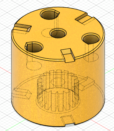
¶ Part types
The Starkiller parts use the following naming scheme: SK{N}{T}{B}
Variables N T and B configure the different options:
| Name variable | Meaning | Possible values |
|---|---|---|
| N | Number of stages to replace | 1-3 |
| T | Number of teeth of the sun gear of the top stage (towards the shaft) | 11, 17 |
| B | Number of teeth of the sun gear of the bottom (towards the motor) | 11, 17 |
If N is 1, then B and T must be the same as we are replacing a single planetary stage. It is not possible to have, for example, part SK11117 or SK11711.
¶ Motor Modding and Configuration
To obtain different configuration, we can lock one or more of the planetary stages to 1:1 ratio.
¶ 84 RPM Motor
| Output RPM | 84 | 312 | 435 | 1150 | 1620 | 6000 |
|---|---|---|---|---|---|---|
| Stage 3 (Shaft) 17T 3.7:1 |
 |
|
|
 Replace with Replace with SK11717 |
|
 Remove Remove |
| Stage 2 11T 5.2:1 |
|
|
Replace with SK11111 |
|
Remove |
Remove |
| Stage 1 (Motor) 17T 3.7:1 |
|
Replace with SK11717 |
|
Replace with SK11717 |
Replace with SK21117 |
Replace with SK31717 |
¶ 117 RPM Motor
| Output RPM | 117 | 435 | 1620 | 6000 |
|---|---|---|---|---|
| Stage 3 (Shaft) 17T 3.7:1 |
|
|
|
Remove |
| Stage 2 17T 3.7:1 |
|
|
Remove |
Remove |
| Stage 1 (Motor) 17T 3.7:1 |
|
Replace with SK11717 |
Replace with SK21717 |
Replace with SK31717 |
¶ 223 RPM Motor
| Output RPM | 223 | 1150 | 6000 |
|---|---|---|---|
| Stage 2 (Shaft) 11T 5.1:1 |
|
|
Remove |
| Stage 1 (Motor) 11T 5.2:1 |
|
Replace with SK11111 |
Replace with SK21111 |
¶ 312 RPM Motor
This motor ships in two different stacking options. Open up your motor to see which you have.
| Output RPM | 312 | 1150 | 1620 | 6000 |
|---|---|---|---|---|
| Stage 2 (Shaft) 17T 3.7:1 |
|
Replace with SK11717 |
|
Remove |
| Stage 1 (Motor) 11T 5.2:1 |
|
|
Replace with SK11111 |
Replace with SK21711 |
| Output RPM | 312 | 1150 | 1620 | 6000 |
|---|---|---|---|---|
| Stage 2 (Shaft) 11T 5.2:1 |
|
|
Replace with SK11111 |
Remove |
| Stage 1 (Motor) 17T 3.7:1 |
|
Replace with SK11717 |
|
Replace with SK21117 |
¶ 435 RPM Motor
| Output RPM | 435 | 1620 | 6000 |
|---|---|---|---|
| Stage 2 (Shaft) 17T 3.7:1 |
|
|
Remove |
| Stage 1 (Motor) 17T 3.7:1 |
|
Replace with SK11717 |
Replace with SK21717 |
¶ 1150 RPM Motor
| Output RPM | 1150 | 6000 |
|---|---|---|
| Stage 1 11T 5.2:1 |
|
Replace with SK11111 |
¶ 1620 RPM Motor
| Output RPM | 1620 | 6000 |
|---|---|---|
| Stage 1 17T 3.7:1 |
|
Replace with SK11717 |
¶ Configuring the CAD
The CAD provided in our repository is modelled in Fusion360 and makes heavy use of the parametric features and presets. While we recommend using Fusion360 parameters for tuning, we also provide STEP files for use in other CAD software.
We recomend that you grab the CAD file from our github repository. Even though we also provide STL files, the tolerances might not fit well depending on your printer and you might have to re-configure the CAD for your specific setup.
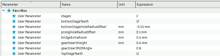
The CAD file contains lots of parameters that can be configured. The most important are set to favourites and should be configured to your setup:
| Parameter | Meaning |
|---|---|
stages |
Number of stages to replace (N variable) |
bottomStageTeeth |
Number of teeth on the bottom stage sun gear (B variable) |
topStageTeeth |
Number of teeth on the bottom stage sun gear (T variable) |
bottomStageHoleRadiusOffset |
A radius offset added to bottom gear hole, to aid with tolerance and part fir |
prongHoleRadiusOffset |
A radius offset added to top prongs hole, to aid with tolerance and part fit |
bottomStageHoleSmallGearRadiusOffsetComp |
A radius offset added to bottom gear hole only for the 11T variant |
bridgeExtraRoom |
Amount of material to remove at the end of holes to compensate bridge sag |
gearInsertHeight |
Height of the tooth making contact with the bottom gear |
gearInsertPcOfAngle |
How thick the tooth making contact with the bottom gear should be. Must be between 0 and 1. |
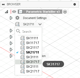
You do not need to set the N, T and B variables manually in the Parameters window. You can use the Configuration menu to switch between part profiles. This setting only changes the first three parameters described above and is a shortcut to switch between the different part numbers.
 |
|---|
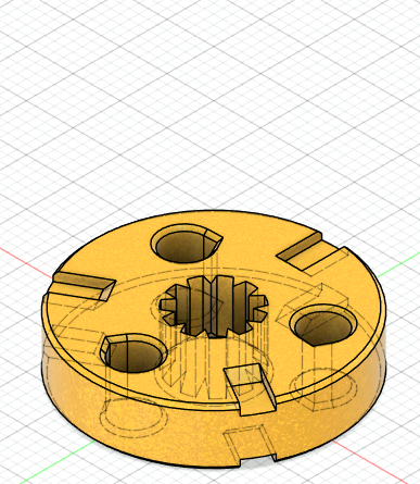
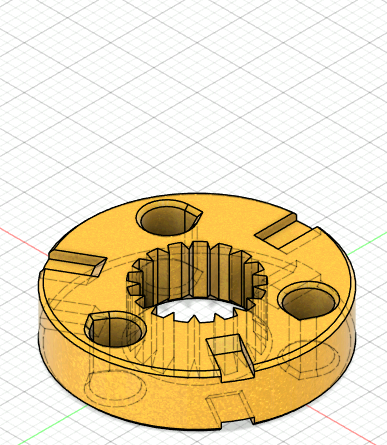
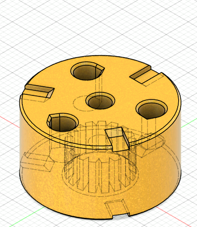
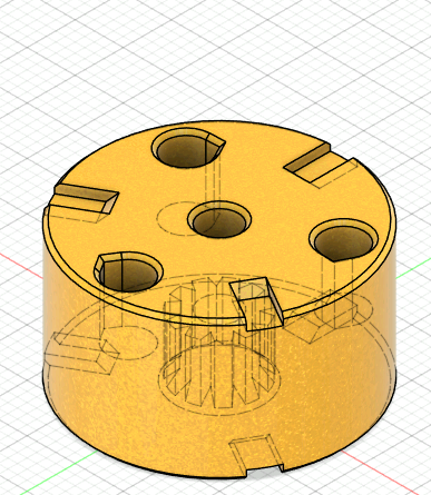
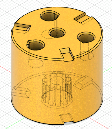
¶ Example CAD configurations
SK11111 |
SK11717 |
SK21117 |
SK21711 |
SK31111 |
SK31717 |
|---|---|---|---|---|---|
 |
 |
 |
 |
 |
 |
¶ Print settings
We STRONGLY recommend that you tune your tolerances by modifying the CAD parameters. If you MUST use the pre-exported STL files to print, use the horizontal expansion (often also called XY compensation) setting in your slicer to adjust the fit. Prioritize getting a good fit for the bottom gear. Loose prongs are OK (will just introduce play) but a loose gear will not work.
We also provide STL's with oversized prong holes for cases where a good gear fit will mean the prong holes are much to small. The files are available in the STL folder.
To properly assemble, we must tailor the tolerances to your printer. We want a good contact with the gears without any backlask or too much tightness.
Having the print too tight around the gear can cause the gear to "dig" into one side of the print and sit off-center. Backlash on the gear will cause the fit to wear over time and become loose.
You should first calibrate your 17T gear fit. Print the SK11717, adjusting the bottomStageHoleRadiusOffset CAD parameter until it fits. After you get a good fit (relatively tight, not require hammer or power tools to assemble, no play) you can move on to calibrate the 11T gear fit using the SK11111 configuration and adjusting bottomStageHoleSmallGearRadiusOffsetComp.
While calibrating the 17T and 11T gears, you can also adjust prongHoleRadiusOffset to calibrate the planetary prongs hole size. Same rules apply here: no play, easy to assemble by hand.
If your printer has very aggressive smoothing due to input shapers, you can decrease gearInsertPcOfAngle to about 0.7 to get sharper teeth in the internal gear.
¶ Print orientation
ABS is strongly recommended for this application. It has both wear and temperature resistance. It is not unusual for FTC motors to get hot, and we fear that PLA might soften and fail.
The SK1 series parts cand be printed flat on the bed on nearly any orientation. We prefer to print them exactly as in CAD, as the first layer squish can be compensated by the chamfer of the bottom gear.
The SK2 and SK3 series must be printed upside-down due to having a hole at the center. The hole makes it easy to remove the gear when dissasembling the modded gearbox by pushing with a M4 screw.
A high (5-6) number of walls is recommended. To ensure stability at high RPM's, the infill should be as uniform as possible. We suggest going for Gyroid 30% with a small line width (105% of nozzle size). No supports are required for any configuration.
Set the seam placing mode to aligned. This will place the seam in the teardrop shape of the prongs hole and improve tolerances for prong contact.
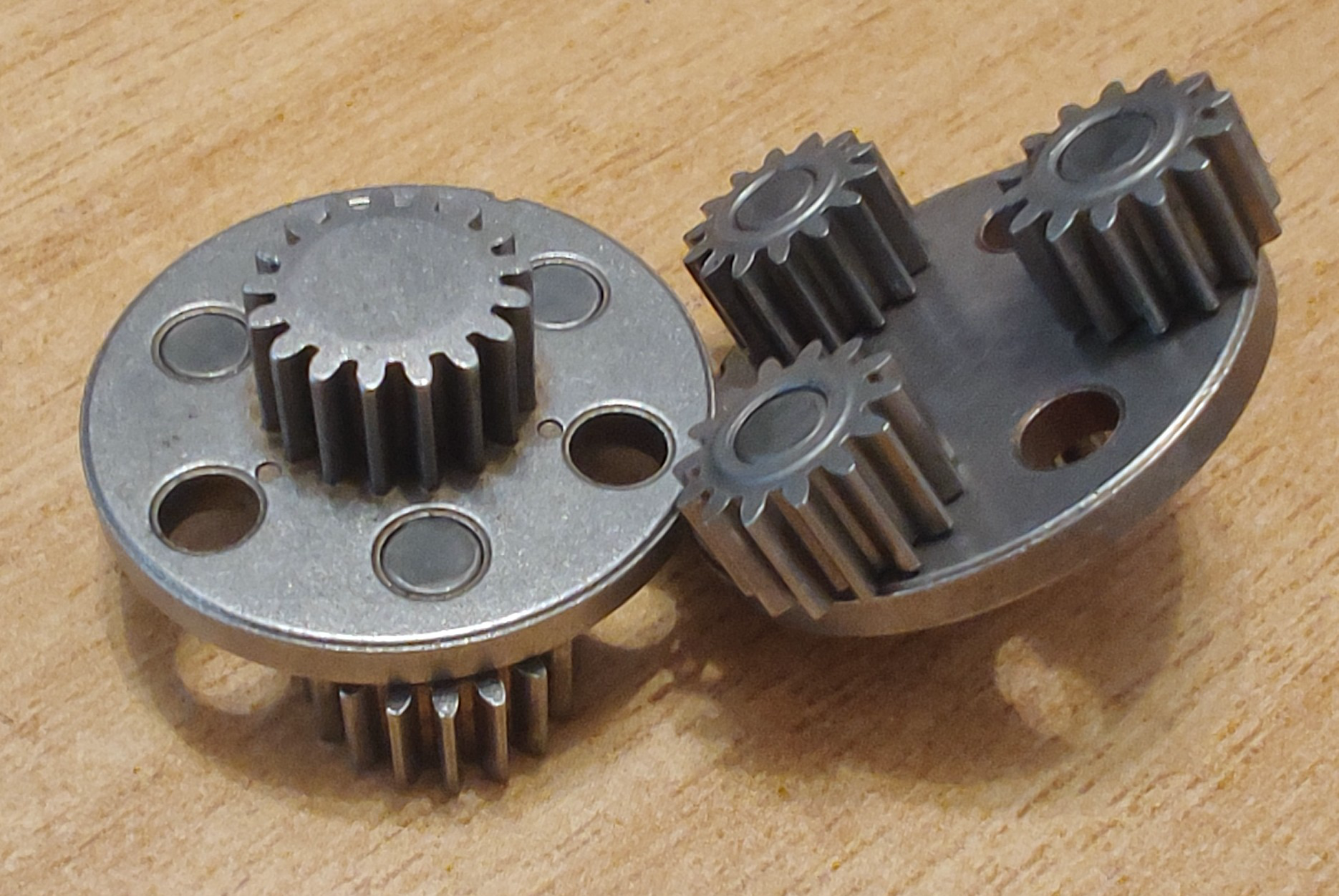
¶ Post-assembly steps
During dissasembly, the factory grease on the gears might catch dust or other particles.
To ensure smooth operation, we need to clean the mechanism of the old, dirty grease and add new lubricant.
We have found that Isopropyl alcohol and a plastic brush work well for cleaning out the old grease.
 |
|---|
| Clean gears |
Avoid leaving the gears ungreased for a long time. Rust might form on the surface due to oxygen and humidity, especially that we do not know what grade of steel Gobilda uses for these gears.
Don't forget to grease both the gears and the prongs! The gears rotate around the prongs and if this interface is not lubed, it will wear out causing backlash in the system, or even locking up completely due to metal chips.
Any kind of thick, tacky grease should be good. We prefer LiquiMoly LM47.
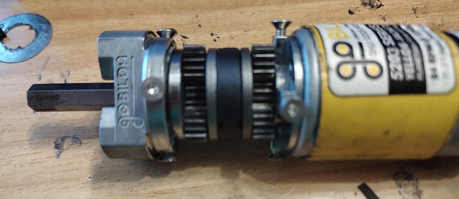
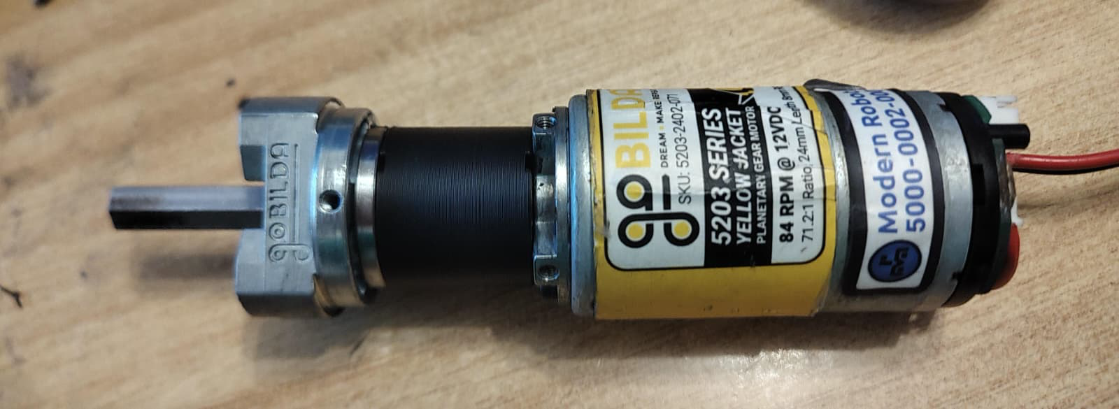
¶ Example modded motor
Conversion from 84 RPM to 435 RPM by replacing the center planetary with SK11111 |
Conversion from 84 RPM to 6000 RPM by replacing all the stages with SK31717 |
|---|---|
 |
 |